15
/
33
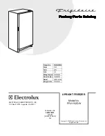
The following is details for connection of computer board and ports;
Mark “1” in the above figure is connecting port for power line to connect power line; mark “2” in the
above figure is sensor port to connect sensor line.
3. Installation steps for control board
Installation shall be according to 2-4 disassembly steps oppositively.
Summary of Contents for DW-25L92
Page 6: ...6 33 Product appearance ...
Page 7: ...7 33 ...
Page 8: ...8 33 ...
Page 9: ...9 33 Dimensions DW 25 L92 DW 40L92 DW 40L188 DW 25L300 DW 40L262 ...
Page 10: ...10 33 Product Specifications ...
Page 11: ...11 33 ...
Page 19: ...19 33 System Schematic Diagram ...
Page 20: ...20 33 System Circuit Diagram ...
Page 24: ...24 33 product nameplate ...
Page 25: ...25 33 ...


