background image

(5)

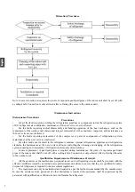
In case the vacuum state cannot be reached, vacuumizing shall be carried out from numerous positions, to

pump the refrigerant in each part of the system out;
(6)

It shall be guaranteed that the capacity of cylinders is sufficient before recovery;

(7)

The recovery equipment shall be started and operated as per the operation instructions of the manufacturer;

(8)

The cylinder cannot be charged too full. (The refrigerant charged cannot exceed 80% of the capacity of

cylinders)
(9)

The maximum operating pressure of cylinders cannot be surpassed even only lasting for a short term;

(10) After refrigerant charging is completed, the cylinder and equipment must be evacuated rapidly, and all the
stop valves on the equipment must be closed;
(11) Before purification and tests, the refrigerant recovered cannot be charged into another refrigeration system.

Note:
The air conditioner shall be marked (with dates and signature) after being scrapped and the refrigerant is
discharged. It shall be guaranteed that the sign on the air conditioner can reflect the flammable refrigerant
charged inside.

Recovery

During maintenance or scrapping, the refrigerant inside the refrigeration system needs to be cleared. It is 

recommended that the refrigerant be cleared thoroughly. 

The refrigerant can only be charged into a dedicated cylinder, the capacity of which shall match with the 

refrigerant amount charged in the whole refrigeration system. All cylinders to be used are designated for the 
recovered refrigerant and labeled for that refrigerant (Dedicated Cylinder for Refrigerant Recovery). The cylinders 
shall be equipped with pressure relief valves and stop valves under favorable state. The empty cylinder shall be 
vacuumized before usage and be kept under normal temperature if possible.  

The recovery equipment shall always be under favorable working state, and be equipped with operation 

instructions, to facilitate information search. The recovery equipment shall be applicable to the recovery of 
flammable refrigerant. Moreover, weighing apparatus under available state with measurement certificates shall be 
equipped. In addition, removable attachment joints free from leakage shall be used as the hose, and shall always 
be under favorable state. Whether the recovery equipment is under favorable state and is properly maintained and 
whether all the electrical components are sealed shall be checked before usage, to avoid fire in case of refrigerant 
leakage. If you have any question, please consult the manufacturer.  

The refrigerant recovered shall be delivered back to the manufacturer in appropriate cylinders, with 

transporting instructions being attached. Mixing of refrigerant in recovery equipment (especially the cylinders) is 
not allowed.  

During transporting, the space in which the flammable refrigerant air conditioners are loaded cannot be 

sealed. Anti-static measures shall be taken for the transporting vehicles if necessary. Meanwhile, during the 
transporting, loading and unloading of air conditioners, necessary protective measures shall be taken, to protect 
the air conditioner from being damaged.  

During removal of the compressor or clearing of the compressor oil, it shall be guaranteed that the 

compressor is vacuumized to a proper level, to ensure no residual flammable refrigerant is left inside the 
lubricating oil. The vacuumizing shall be completed before the compressor is delivered back to the manufacturer. 
The vacuumizing can only be accelerated by heating the compressor housing through electrical heating. Safety 
shall be guaranteed when the oil is discharged from the system.  

11

Summary of Contents for 1U09MECFRA

Page 1: ...2S2SM1FA 1U50S2SJ2FA 1U25YEGFRA 1U35YEGFRA 1U50MEGFRA 1U20YEEFRA 1U25YEEFRA 1U35MEEFRA 1U50MEEFRA 1U68REEFRA 1U25BEEFRA 1U25JEJFRA 1U35JEJFRA 1U50REJFRA 1U25YEGFRA H 1U35YEGFRA H 1U25YEMFRA 1U35YEMFRA 1U50MEMFRA 1U68REMFRA 1U68RENFRA 1U25YEFFRA C 1U35YEFFRA C 1U50MEMFRA C 1U68RENFRA C 1U25MECFRA 3 1U35MECFRA 3 1U50JECFRA 3 1U25S2SM1FA NR 1U35S2SM1FA NR R N A F 2 J S 2 S 0 5 U 1 R N A R F E E B 5 2...

Page 2: ......

Page 3: ...nts 3 Installation Instructions 3 Relocation Procedures 7 Maintenance Instructions 7 Scrapping and Recovery 10 Indoor Outdoor Unit Installation Drawings 12 Safety Precautions 13 Read Before Installation 17 Installation Procedure 20 Outdoor Unit Troubleshooting 25 Warning 1 ...

Page 4: ...r can easily nd it Install the air conditioner in accordance with the instructions in this installation manual Be sure to use only the specified accessories and parts for installation work Install the air conditioner on a foundation strong enough to withstand the weight of the unit Electrical work must be performed in accordance with relevant local and national regulations and with instructions in...

Page 5: ...ol cover Voltage 230V Climate T1 GWP value 675 2 2014 53 EU RED 2014 517 EU F GAS 2009 125 EC ENERGY 2010 30 EU ENERGY 2006 1907 EC REACH RoHS conditioning system treatment of the refrigerant of oil and of other part must be done by a qualified installer in accordance with relevant local and national legislation Air conditioners must be treated at a specialized treatment facility for reuse recycli...

Page 6: ...shers or other suitable fire extinguishing apparatus within the period of validity shall be equipped inside the driver s cab 8 Orange white or red white reflective stripes shall be pasted on the sides and tail of the transporting vehicles to remind the vehicles behind of keeping distance 9 The transporting vehicles shall run at a constant speed and heavy acceleration deceleration shall be avoided ...

Page 7: ...ire source and oil heater shall be avoided below the indoor unit 4 The power supply shall be provided with earthing wire and be reliably earthed 5 While punching the wall with an electric drill whether embedded water electricity gas pipelines are designed at the hole preset by the user shall be verified in advance It is recommended that the through wall holes reserved shall be used as much as poss...

Page 8: ...cting solution The pressure shall be maintained for more than 5 minutes and then whether the system pressure is reduced or not shall be observed In case the pressure is reduced leakage can be identified After the leak point is handled the steps above shall be repeated After the evaporator of the indoor unit is connected to connecting piping nitrogen shall be charged for pressure maintaining and le...

Page 9: ...stallation is firm or not The unit may fall vibrate or make a noise Whether the inspection on air leakage is completed The refrigerating capacity heating capacity may be insufficient Whether the unit is fully insulated Condensation or drip may occur Whether the drainage is smooth or not Condensation or drip may occur Whether the power voltage is identical to that marked on the nameplate Failure ma...

Page 10: ...container internal refrigeration pipelines and refrigeration elements the maintenance at the user s site is allowed including the cleaning and dredging of the refrigeration system requiring no disassembly of refrigeration elements and no welding In case replacement of gas liquid pipes is required during maintenance the joint of evaporator gas liquid pipes of the indoor unit shall be cut off with a...

Page 11: ... Nitrogen cylinders acetylene cylinders and oxygen cylinders shall be placed separately The distance between the gas cylinders above and the working area involved in open fire shall be at least 6m The anti backfire valve shall be installed for the acetylene cylinders The color of the acetylene cylinders and oxygen cylinders installed shall meet the international requirements The warning sign of No...

Page 12: ... the refrigeration system shall be earthed The refrigerant charged shall be of the type and volume specified on the nameplate Excessive charging is not allowed After maintenance of the refrigeration system the system shall be sealed with a safe manner The maintenance in progress shall not damage or lower the original class of safety protection of the system Maintenance of Electrical Components Par...

Page 13: ... During the use of refrigerant charging tools cross contamination of different refrigerants shall be avoided The total length including the refrigerant pipelines shall be shortened as much as possible to reduce the residual of refrigerant inside The cylinders of refrigerant shall be kept upright Before refrigerant charging the refrigeration system shall be earthed A label must be pasted on the ref...

Page 14: ...e vacuumized before usage and be kept under normal temperature if possible The recovery equipment shall always be under favorable working state and be equipped with operation instructions to facilitate information search The recovery equipment shall be applicable to the recovery of flammable refrigerant Moreover weighing apparatus under available state with measurement certificates shall be equipp...

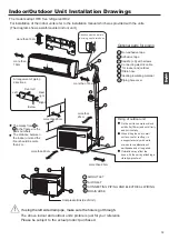
Page 15: ... attaching a vibration proof mat The marks from to in the gure are the parts numbers The distance between the indoor unit and the oor should be more than 2m The models adopt HFC free refrigerant R32 more than 10cm more than 15cm more than 10cm more than 20cm more than 20cm more than 25cm more than 60cm A G A F C E D G B Arrangement of piping directions Rear left Left Rear right Right Below G Atten...

Page 16: ...WARNING CAUTION N Open the window and well ventilated the room explosion proof fuse 13 ...

Page 17: ...32 3 fire or explosion will be caused fire or explosion fire or explosion fire or explosion fire or explosion fire explosion 14 ...

Page 18: ...R32 2 3 R 2 3 R R32 R32 R32 R32 R32 15 ...

Page 19: ...c shock fire or explosion Install a explosion proof breaker for current leakage at the power source to avoid the risk of the electric shock Do not use large capacity fuses steel wire or copper wire Damaging the unit fire smoke or explosion will be caused otherwise 16 ...

Page 20: ...R32 R32 R32 R32 R32 R32 R32 R32 R32 17 ...

Page 21: ...3 R32 R32 R32 R32 R32 R32 R32 18 ...

Page 22: ...R32 R32 R32 R32 R32 R32 R32 R32 10A HFC 410A 19 ...

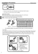
Page 23: ...NO Wind direction Air outlet Cushion rubber 4 Installation dimension Unit mm 20 Power Wiring Terminal Power Wiring Distribution Hole The values of The installation dimension are shown in table 3 ...

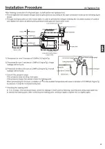
Page 24: ...pe has to be lengthened the refrigerant should be charged according to E g m But the charge of refrigerant must be conducted by professional air conditioner engineer Before adding additional refrigerant perform air purging from the refrigerant pipes and indoor unit using a vacuum pump then Spanner Forced fastening without careful centering may damage the threads and cause a leakage of gas Pipe Dia...

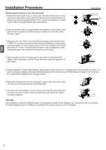
Page 25: ...22 ...

Page 26: ...23 R32 R32 ...

Page 27: ...c type of T 25A 250V The explosion proof breaker of the air conditioner should be all pole switch The distance between its two contacts should not be no A explosion proof breaker must be installed 24 table6 1 ...

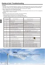
Page 28: ...86 532 8893 7937 Website www haierhvac eu motor 3 Outdoor Unit 2 9 15 8 12 10 5 13 19 1 18 4 11 25 25 25 110 Suction temperature sensor failure When the The wiring of compressor is wrong or the connection is poor 17 16 Lack of refrigerant Check if there is leakage in the unit m 25 0 ...

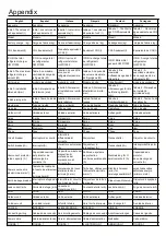
Page 29: ...o Gas pipe Tubo de gas Tubo per gas Tuyau de gaz Gasleitung Tubo de gás Outdoor Unit Unidad exterior Unidade exterior Unité extérieure Außengerät Unidade exterior Amax A máx A massimo Amax Amax Amax Bmax B máx B massimo Bmax Bmax Bmax Bmin Bmínimo B minmo Bmin Bmin Bmin item Elemento Oggetto Élément Pos item Phase Fase Stato Phase Phase Fase Interruttore Circuit breaker Interruptor de circuito dif...

Page 30: ...ς Cijevi za teku ine Vloeistofleiding Жидкостная труба Rura na gaz Gaz borusu Σωλήνας αερίου Cijev za plin Gasbuis Газовая труба Urządzenie Dış ünite Εξωτερική μονάδα Vanjska jedinica Buitenunit Наружный блок zewnętrzne Amaks Amax A υεγ Amax Amaximum Amax Bmaks Bmax B υεγ Bmax Bmaximum Bmax Bmin Bmin B ελάχιστο Bmin Bmin Bmin Pozycja Öge Stavka Punt пункт Faza Faz Φάση Faza Fase Фаза Автоматически...

Page 31: ...0 53 0 36 1U50MEGFRA H 0 9 0 61 1U25BEEFRA NR 0 5 0 34 1U35MEEFRA NR 0 62 0 42 Unit model M kg Unit model M kg Unit model M kg Unit model M kg Unit model M kg Unit model M kg 1U25S2SM1FA 0 95 1U50MEGFRA 1 3 1U35YEMFRA 0 8 1U25S2SM1FA NR 0 95 1U25MECFRA 3 1 04 1U35MEEFRA NR 0 92 1U35S2SM1FA 1 24 1U20YEEFRA 0 8 1U50MEMFRA 1 3 1U35S2SM1FA NR 1 24 1U35MECFRA 3 1 04 1U42S2SM1FA 1 24 1U25YEEFRA 0 85 1U6...

Page 32: ...EFRA 1U35S2SM1FA 1U35YEGFRA 1U35S2SM1FA NR 1U35YEMFRA 1U35YEFFRA C 1U42S2SM1FA 1U35YEGFRA H 1U35MEEFRA NR 1 20 15 1 5 20 30 1U50MEEFRA 1U50JECFRA 3 1U50MEGFRA 1U50MEMFRA C 1U50MEMFRA 1U50S2SJ2FA NR 1U50REJFRA 1U50S2SJ2FA 1U68REEFRA 1U68RENFRA C 1U68REMFRA 1U68RENFRA 1U50MEGFRA H 1 25 20 2 5 25 30 item Model Phase Circuit breaker Power source wire size minimu m mm Earth leakage breaker Model 1U25S2...

Page 33: ... 1U50MEEFRA FOR 1U25YEMFRA 1U35YEMFRA 1U25JEJFRA 1U35JEJFRA 1U50REJFRA 1U50MEMFRA 1U25BEEFRA 1U25S2SM1FA NR 1U35S2SM1FA NR 1U25YEFFRA C 1U35YEFFRA C 1U50MEMFRA C 1U25MECFRA 3 1U35MECFRA 3 1U50JECFRA 3 1U25YEGFRA H 1U35YEGFRA H 1U50MEGFRA H 1U25BEEFRA NR 1U35MEEFRA NR 1U50S2SJ2FA 1U68REEFRA 1U68REMFRA 1U68RENFRA 1U50S2SJ2FA NR 1U68RENFRA C To Indoor unit Outdoor unit 1 2 3 C 1U09MECFRA 1U12MECFRA 1...

Page 34: ...此框内由厂家印说明书专用号一维码 厂 家生成 宽51 高12mm 此绿框仅用 于定位 实际印刷时删掉 0010589581 ...

Reviews: