background image


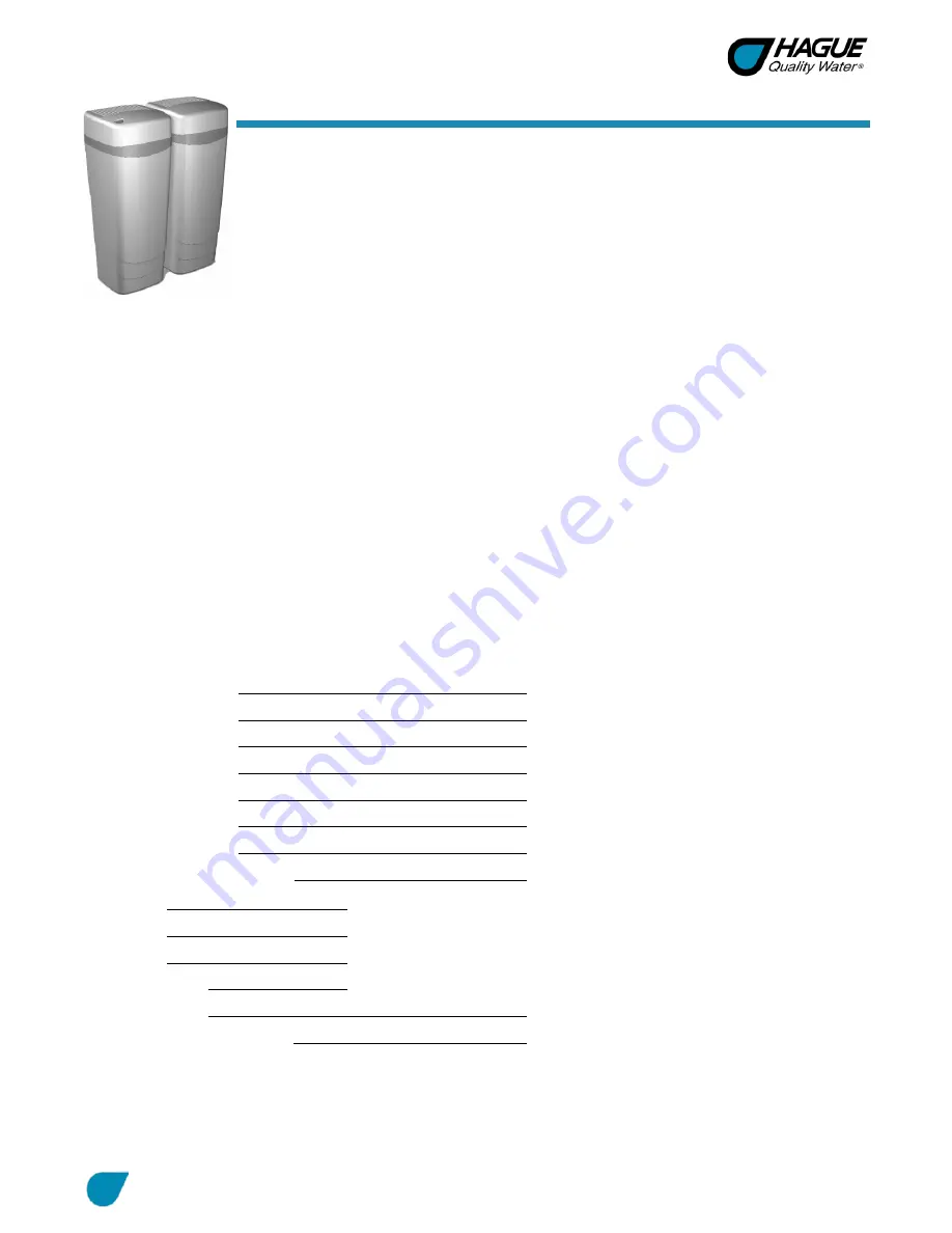
WaterMax ST Series Owner’s Manual 

5/11/2018 

General Information 

Congratulations 

on choosing a superior Hague water treatment appliance! Soon you and 

your family will be enjoying clean, clear water. Use this guide to attain the maximum benefit 

from your appliance. As an owner, you may find the first few pages to be the most helpful in 

solving your needs. If you have trouble with the operation of your appliance, see 

Troubleshooting in the back of this manual or contact your independent Hague dealer. 
Warning: This appliance must be applied to potable water only. It is recommended that an 

independent Hague dealer install and maintain this appliance. 

Note: The manufacturer reserves the right to make specification and product changes without prior notice. 
This manual is for installation, operation, and maintenance of the following water conditioning appliance 

models: 


WaterMax

®

 3MAQ* 


WaterMax

®

 3MDQ 


WaterMax

®

 2AJQ 


WaterMax

®

 3BAQ* 


WaterMax

®

 2AMQ* 


WaterMax

®

 1AAN 


WaterMax

®

 3BEQ* 


WaterMax

®

 2APQ* 


WaterMax

®

 3MXQ* 


WaterMax

®

 2AKQ 


*Tested by WQA 

If your specific model is not listed here, your appliance has been customized to solve additional water 

conditioning problems that you may have. Your dealer will be happy to explain any additional special features. 
Note: For Model 2AJQ, be sure to read 2AJQ Replenishment Procedure. For Model 1AAN, be sure to read 

1AAN WaterMax

®

 Iron Filter Sizing Formula and Iron Filter and Potassium Permanganate Feeder Installation 

Guide

For Owner’s Reference 

Date of Installation:  


Model Number: 


Serial Number

1


Installer’s Signature:   
Dealership Name: 


Dealership Address:    


Dealership Phone Number:  


Hardness:    


Iron: 


pH: 


Water Pressure:   


Water Temp: 


Returned Warranty Card Date

2

:   


1

 The serial number is located on the left front support panel. 

2

 Completely fill out the Warranty Card and return it by mail to ensure that the appliance is registered with the factory and the warranty 

becomes validated.  

Owner Information 

Summary of Contents for WaterMax ST Series

Page 1: ...WATER CONDITIONING APPLIANCE ST SERIES OWNER S MANUAL AND INSTALLATION GUIDE VERSION 1 1...

Page 2: ...n algae sulfur tannins organic matter or other unusual substances then unless the appliance is represented as being capable of handling these substances in the appliance specifications other special t...

Page 3: ...tions 10 Installation Steps and Start Up Procedures 11 Bypass Valve 14 Blending Valve 15 Setting and Using the Controller 15 Service Settings 16 Salt Depths 21 2AJQ Replenishment Procedure 22 1AAN Wat...

Page 4: ...iance models WaterMax 3MAQ WaterMax 3MDQ WaterMax 2AJQ WaterMax 3BAQ WaterMax 2AMQ WaterMax 1AAN WaterMax 3BEQ WaterMax 2APQ WaterMax 3MXQ WaterMax 2AKQ Tested by WQA If your specific model is not lis...

Page 5: ...resent in the water supply the appropriate Hague filter can eliminate this problem See Filter Specifications 6 The appliance may be disinfected with 5 25 sodium hypochlorite which is the active ingred...

Page 6: ...et the Service Settings during installation of the appliance Figure 1 Smart Touch Controller Button Function Ok Sets the information and moves to the next screen Back Navigates to the previous screen...

Page 7: ...Set Regeneration Time Display reads Regeneration Time followed by the current regeneration time that is set Ex 02 00am To Change the Regeneration Time A Enter the desired regeneration time hh mm B Ta...

Page 8: ...e current setting for the number of people in the household Ex 4 To Change the Number of People A Enter the number of people in the household B When the desired number of people is displayed press Ok...

Page 9: ...lloidal Iron Not dissolved yet stays in suspension A softener cannot remove this type of iron If the water supply contains ferrous iron a commercially available resin bed cleaner should be used every...

Page 10: ...heater Do Not 1 Do not install if checklist items are not satisfactory See Checklist Before Installation 2 Do not install if the incoming or outlet piping water temperature exceeds 120 F 49 C See Wate...

Page 11: ...igure 2 as a guide The diagram in Figure 2 applies to basement slab crawl space and outside installations G For most installations install the appliance after the pressure tank and any water filter ap...

Page 12: ...of the overflow fitting Maintain a minimum 2 inch 5 cm air gap between the overflow line and the flood level rim of the waste receptor to prevent back siphoning The gravity line cannot be run overhea...

Page 13: ...automatically refill the correct amount of water into the brine tank B Ensure that the bypass is in Service position C Ensure that the salt dosage is set as recommended for the application D Initiate...

Page 14: ...r at the test port to verify soft water G Place the covers on both of the cabinets Bypass Valve The bypass valve can isolate the appliance should the appliance malfunction or leak It can also permit t...

Page 15: ...ed water line Note If the appliance is installed for barium and or radium reduction the blending valve must remain in the fully closed position at all times Setting and Using the Controller The contro...

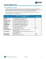
Page 16: ...ee Operating Modes 2 Hardness Grains Enter hardness test results 1 to 199 grains or 0000 to 3999 mg L 40 Iron ppm Enter iron test results 0 to 99 ppm mg L 0 Manganese ppm Enter manganese test results...

Page 17: ...ersion number For Reference Only V1 1 H Date Enter Installation Date Format MMDDYY 0 H Number of People Enter number of people in the household 1 to 50 4 H Hardness grains Enter hardness test results...

Page 18: ...tion Time In Customer Settings select the days on which you would like the unit to regenerate Mode 2 Demand Delayed Mode When the appliance is in the Patented Savematic Demand Delayed mode it will reg...

Page 19: ...27 27 41 38 27 27 27 27 Backwash 2 minutes 3 3 3 3 3 2 2 2 2 Capacity grains salt lb grams salt kg 23 400 6 2 1 520 2 8 24 600 6 2 1 590 2 8 24 600 6 2 1 590 2 8 38 300 9 6 2 480 4 4 23 100 8 5 1 500...

Page 20: ...816 1 2 12 600 2 7 816 1 2 12 600 2 7 816 1 2 19 700 4 2 1 280 1 9 12 000 2 7 778 1 2 3 Salt Setting Backwash 1 minutes 1 1 1 17 27 Brine Rinse minutes 27 27 27 41 27 Backwash 2 minutes 3 3 3 3 2 Cap...

Page 21: ...4 18 4 6 0 2 7 11 7 8 30 2 6 0 2 7 8 7 8 22 6 6 2 2 8 12 30 5 6 2 2 8 8 7 8 22 6 6 5 2 9 12 3 8 31 4 6 5 2 9 9 22 9 8 5 3 9 14 3 4 37 5 8 5 3 9 9 5 8 24 4 9 0 4 1 15 3 8 39 1 9 0 4 1 9 7 8 25 1 9 3 4...

Page 22: ...4 inch socket Replenishment Procedure The replenishment procedure is as follows Step 1 Turn Off the Water A Turn off the water to the appliance B Open a tap to depressurize the appliance C Close the...

Page 23: ...nk With Water A Open the main water valve B Slowly fill the tank with water up to the bottom of the fill port C Turn off the water Step 6 Replace Fill Plug A Make sure the threads of the fill port are...

Page 24: ...compensated ppm ___ ppm mg L 9 1 ppm mg L x Gallons per day for one person 75 gallons 284 L 75 gallons 284 L ppm per person per day ____ ppm 682 5 ppm x Number of people in household ____ people 4 pe...

Page 25: ...n of the filter Examine the inlet piping to make sure the pipe is not plugged with lime or iron If the piping is plugged it must be cleaned or replaced Figure 6 Iron Filter and Potassium Permanganate...

Page 26: ...cover of the feeder as well as the instructions on the potassium permanganate container Step 5 Set Air Check Draw Tube A Allow the water to be drawn out of the feeder until the air check draw tube set...

Page 27: ...nal 90256 3 4 inch PVC Adapter optional 90258 Copper Adapter 1 inch optional 4 90251 Bypass Nut 2 5 C0700A Cabinet Overflow 1 6 93245 12V Transformer Power Cord 1 7 54490 Smart Touch Controller Assemb...

Page 28: ...0 Potassium Permanganate Feeder P N PT1424 Part Description Quantity 1 54006 Brine Tank Cover 1 2 90103 Brine Well Cap 1 3 54625 Safety Shutoff Assembly see Figure 18 1 4 54007 Support Panel BT 1 5 C0...

Page 29: ...9 O Ring 1 8 93838 O Ring 2 9 54600 Bypass Valve Assembly see Figure 14 1 10 120110 O Ring 1 11 95315 Drive End Cap Assembly see Figure 15 1 95302T BWO Drive End Cap Assembly Backwash only 1 12 54003...

Page 30: ...ed flush into the opening in the valve If the Throat is removed it must be replaced with a new one 53224 Injector Nozzle with Over Mold Gasket Together with the Throat creates the vacuum that draws th...

Page 31: ...sembly all of the above parts 90238 Fill Plug The Fill Plug seals the media access ports in the Media Tank Care should be taken that the O Ring seal area is kept clean and free of debris Also the O Ri...

Page 32: ...sembly also includes items 2 15 1 2 90827 O Ring 1 3 90222 Blending Dial 1 4 90252 Cap Blending Dial 1 5 90802 Screw 5 6 90812 Tubing 4 0 inch 1 7 90226 Test Port Valve 1 8 90828 O Ring 2 9 90264 O Ri...

Page 33: ...mproper upside down assembly Do not force the connector past the stops 54320 Plastic Turbine Axle Sits on a ridge in the Main Control Valve side of the outlet stream of the Bypass Valve Assembly Needs...

Page 34: ...1 5 90809 Screw self tapping 2 6 93219 Piston Slide Cam Cover 1 7 93217 Piston Slide Cam 1 8 93583 Drive End Cap 1 9 54202 Piston Slide 1 10 90818 Screw self tapping 2 11 93699R JG Brine Valve Housing...

Page 35: ...an axial or face seal The O Ring sits in a groove in the End Cap This groove must be free of defects such as pits or scratches and also free of debris The smaller diameter seal is accomplished with a...

Page 36: ...ave seat area that must be free of defects such as nicks indentations or debris This seat area ensures a leak free seal for the static O Ring on the Brine Piston If any defects are detected by visual...

Page 37: ...e care should be taken to make sure that the O Ring stays in the groove in the End Cap If misaligned the O Ring can become pinched and leak H2086 Drain Line Flow Control The Drain Line Flow Control DL...

Page 38: ...Shutoff Assembly Figure 18 Safety Shutoff Assembly Part Description Quantity 1 54225 Push Connect Safety Shutoff 1 2 56018 Float 1 3 54160 Air Check Draw Tube 1 54625 Entire Assembly all of the above...

Page 39: ...ended power outage Reset the time of day Water hardness has increased Re test the water and re enter a new setting number Not metering water Flow should be indicated with water usage If no flow see be...

Page 40: ...or replace injector Replace throat if removed Not regenerating in proper sequence Magnet disk defective Replace magnet disk Defective controller Replace controller Salty water pink water from iron fil...

Page 41: ...alt Dosage Capacity at That Dosage 3MAQ 5 200 grains lb 738 grams kg 1 1 lb 0 5 kg 5 700 grains 369 grams 3BAQ 5 400 grains lb 772 grams kg 1 1 lb 0 5 kg 6 000 grains 389 grams 3BEQ 5 400 grains lb 77...

Page 42: ...1 27 31 102 46 31 46 119 47 31 47 117 4 Salt Setting Total length of reg Min gal L 36 26 36 100 36 29 36 110 36 29 36 110 53 35 53 132 64 39 64 148 Shipping weight lb kg 135 61 152 69 152 69 168 76 15...

Page 43: ...te pellet cube style or solar salt Drain Line Minimum I D 1 2 inch 1 3 cm Height inches cm 38 1 4 97 Salt storage capacity lb kg 200 90 Electrical rating 115V 60 cycle Valve Inlet Outlet 1 inch Water...

Page 44: ...S 5 N A N A N A N A Iron ppm 20 N A N A N A N A Minimum pH 7 N A N A 51 N A Media type Manganese Greensand N Activated Carbon E Filter Ag R Calcite Corosex S Multi Grade F Media amount cu ft L 1 25 35...

Page 45: ...WaterMax ST Series Owner s Manual 5 11 2018 45 Certificates...

Page 46: ...WaterMax ST Series Owner s Manual 5 11 2018 46 Certificates Cont...

Page 47: ...WaterMax ST Series Owner s Manual 5 11 2018 47 Notes...

Page 48: ...SF ANSI 44 for Efficiency Softening Performance and the reduction of Barium and Radium 226 228 as verified and substantiated by test data Barium Radium reduction occurs as long as the appliance is sof...

Reviews: