background image

17

8

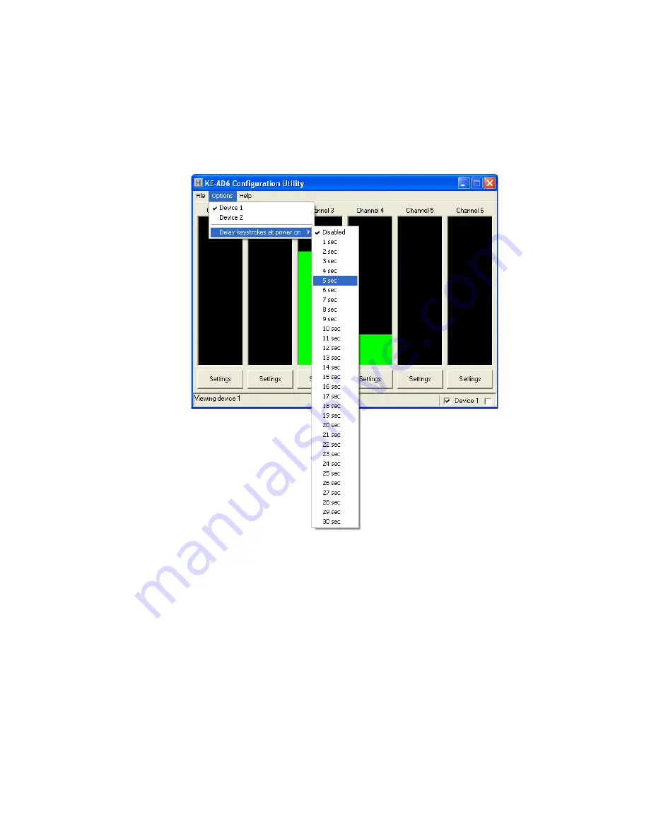
Options Menu Selections

O

ptio

n

 p

a

r

ame

t

e

r

s,


l

o

ca

t

ed


w

ithi

n


a


d

rop

-d

o

wn


l

i

s

t

,


a

r

e


accessed


b

cl

i

ck

i

n

g o

n


“O

ptio

ns”

  i

n

  th

e


u

pp

e

lef

t  

c

or

ne

r o

f

  th

e


ma

i

n


progr

am


sc

r

een.


A


l

i

s

t o

f

 th

ese

 optio

ns,


al

o

n

w

ith 

desc

riptio

ns


o

f

 ho

w

 th

e

y p

e

rt

a

i

n

 to th

e


KEAD

se

t

u

p

,


a

r

e


l

i

s

t

ed


bel

o

w.

Device 1:

 C

l

i

ck

 thi

s

 optio

n

 to 

selec

t th

e


dev

i

ce


w

ith 

an


ID

 o

f

 1

.


See

 p

a

g

e


5,


sec

tio

n


“Sw

it

c

hi

n

Selec

t

ed


Dev

i

ce,”


f

or 

de

t

a

i

ls.

Device 2:

 C

l

i

ck

 thi

s

 optio

n

 to 

selec

t th

e


dev

i

ce


w

ith 

an


ID

 o

f

 2

.


See

 p

a

g

e


5,


sec

tio

n


“Sw

it

c

hi

n

Selec

t

ed


Dev

i

ce,”


f

or 

de

t

a

i

ls.

Delay keystrokes at power on:


T

hi

s

 optio

n


de

t

e

r

m

i

nes


ho

w


l

o

n

g th

e


KEAD

wa

it

s


u

po

n


be

i

n

g po

we

r

ed

  o

n


bef

or

e


be

gi

nn

i

n

g to 

send


ke

y

s

tro

kes.


T

hi

s


can


e

ith

e

be


se

t to 

“D

i

sabled”


or 

a


value

 r

an

gi

n

f

ro

m

 1 

sec

o

nd

 to 

3

sec

o

nds.


If

 thi

s


se

tti

n

i

s


enabled,

 th

e


KEAD

w

i

ll


wa

it th

e


selec

t

ed

 ti

me


be

gi

nn

i

n

a

po

we

r o

n


bef

or

e


send

i

n

an

y progr

ammed

 r

es

po

nses


f

ro

m

 th

e


i

n

p

u

c

h

annels.

Disabling Channels

An

c

h

annels

 th

a

a

r

e


n

ot 

used


s

ho

uld


be


se

t to 

be


d

i

sabled.


T

d

i

sable


a


c

h

annel,

 fi rst open the settings window for the channel

.


Then uncheck the Key

b

oard and Joystick 

Ena

b

led

 check

b

oxes 

(

see  arrows 

b

elow

).

  Once  the  confi guration  is  written  to  the 

device

,

 this channel will 

b

e disa

b

led

.

Summary of Contents for KEAD6

Page 1: ...KEAD6 USB Joystick Interface and Keyboard Encoder User Manual...

Page 2: ...8 Configuring the KEAD6 9 KEAD6 Operating Tips 19 Error Messages 20 Appendix A KEAD6 Specifications 22 Appendix B Using the KEAD6 with Custom Software 23 Accessories 24 Thank you for purchasing the HA...

Page 3: ...the configuration information is retained on the unit even after power is turned off The KEAD6 configuration may be changed using the included software as many times as required for various applicati...

Page 4: ...AD6 emulates both a USB joystick and a standard USB keyboard The KEAD6 may be used in addition to or in place of the system s own keyboard 2 In o a e s C A t C t K d Device ID Jumper Two KEAD6 units m...

Page 5: ...to 1M Potentiometers are connected to the 5V Wiper input and Ground as shown below 3 25 4 Wiper 5V Ground Three Joystick Buttons The four position header on the KEAD6 provides three inputs and a logic...

Page 6: ...e section Computer Connections 2 Insert the CD and save the content to its own folder on the hard drive The CD may now be removed and stored in a safe location for future use 3 Open the folder that wa...

Page 7: ...ID Jumper are both connected to the PC then the KEAD6 EXE program must be set to which device to monitor In the lower right corner of the main screen there are two checkboxes which are used to switch...

Page 8: ...upper left corner of the main program screen This list provides several options that include creating and saving file configurations as well as reading and writing to the KEAD6 A list of these option...

Page 9: ...the current configuration in the selected KEAD6 and display it on the screen Click on Read from KEAD6 with the mouse or press Ctrl R on the keyboard to perform this operation Write to KEAD6 This optio...

Page 10: ...5 section Switching Selected Device for details Device 2 Click this option to select the device with an ID of 2 See page 5 section Switching Selected Device for details Delay keystrokes at power on T...

Page 11: ...he Settings button below the graph of a channel For example if changing channel 1 settings the left most Settings button must be selected The settings window for channel 1 will then appear as shown be...

Page 12: ...okes each channel can be set into several different modes listed below Under step mode the channel becomes sectioned into a number of equal parts where each section can be assigned a different keystro...

Page 13: ...oduceonekeystrokeper step In most cases this setting should be set to off Setting this option to on causes the keystroke for the current step to be held down as if a key on a typical PC keyboard were...

Page 14: ...ow X Y or Z axis Rx Ry or Rz axis Slider Dial Wheel Vx Vy or Vz axis Vbrx Vbry or Vbrz Vno To make a selection open the drop down list by clicking on the down arrow next to the current selection and c...

Page 15: ...re that the keyboard enabled checkbox is checked Change Number of steps to 2 4 8 16 or 32 as shown below The keystrokes these steps produce can be assigned by clicking on a section of the graph and se...

Page 16: ...s determined by the hysteresis setting To place a channel into directional mode open the settings window for the channel Then change Number of steps to Directional as shown below The graph will show t...

Page 17: ...e emulated when the channel value reaches that step To assign keys click on the desired step on the graph A diagram of the keyboard will be displayed as shown below Click on the representation of the...

Page 18: ...check the Ctrl and Alt boxes on the lower left corner of the keyboard diagram then click the Del button shown below Any step in the channel can be modified by one or a combination of Shift Alt or Ctr...

Page 19: ...not used should be set to be disabled To disable a channel first open the settings window for the channel Then uncheck the Keyboard and Joystick Enabled checkboxes see arrows below Once the configura...

Page 20: ...a channel setup click the OK button as shown below To discard any changes made to the channel settings click the Cancel button Note No changes will take place on the KEAD6 itself until the configurati...

Page 21: ...the completed configuration click on Write to KEAD6 under the File menu Be sure that the KEAD6 is connected to the PC Once the KEAD6 is loaded and the KEAD6 EXE program is closed the KEAD6 will begin...

Page 22: ...led at power on or reset only Before using the KEAD6 EXE program visit Microsoft Windows Update and get the latest updates for the operating system This step is important for making sure the PC has th...

Page 23: ...other application and open the file again Error saving file This error message is shown if the KEAD6 EXE program attempts to save a file that is already open in another application or if there is not...

Page 24: ...perating Voltage 5 Volts DC 5 Operating Current 15 ma Typical potentiometers Operating Temp 0 to 70 Degrees C PC Interface USB Potentiometer Range 500 to 1M Appendix A KEAD6 Specifications 2 7 3 0 125...

Page 25: ...ue by the user s custom software utilizing the KEAD6 dll which is located on the included CD ROM A Visual Basic sample program demonstrating how to read the digital values from the KEAD6 inputs is inc...

Page 26: ...w 24 Accessories KE USBMM6 6 foot USB Type A to Type B connecting cable between KEAD6 and PC MTA100 4 12 Cable set for use with KEAD6 Joystick But ton inputs 4 wires each 12 inches long Terminated wit...

Page 27: ...warranty Depending on the state in which you live you may have additional rights Great care has been taken during the assembly testing and burn in of your KEAD6 to ensure its performance If you have a...

Page 28: ...4677 Fax 540 465 4678 Monday through Friday 8 00 am to 5 00 pm EST sales hagstromelectronics com www hagstromelectronics com 1986 Junction Road Strasburg VA 22657 Copyright 2017 HAGSTROM ELECTRONICS...

Reviews: