hager HW+ Series Installation Manual Download Page 31

31

6LE007596Ad

Positions of the drawout circuit breaker in the chassis

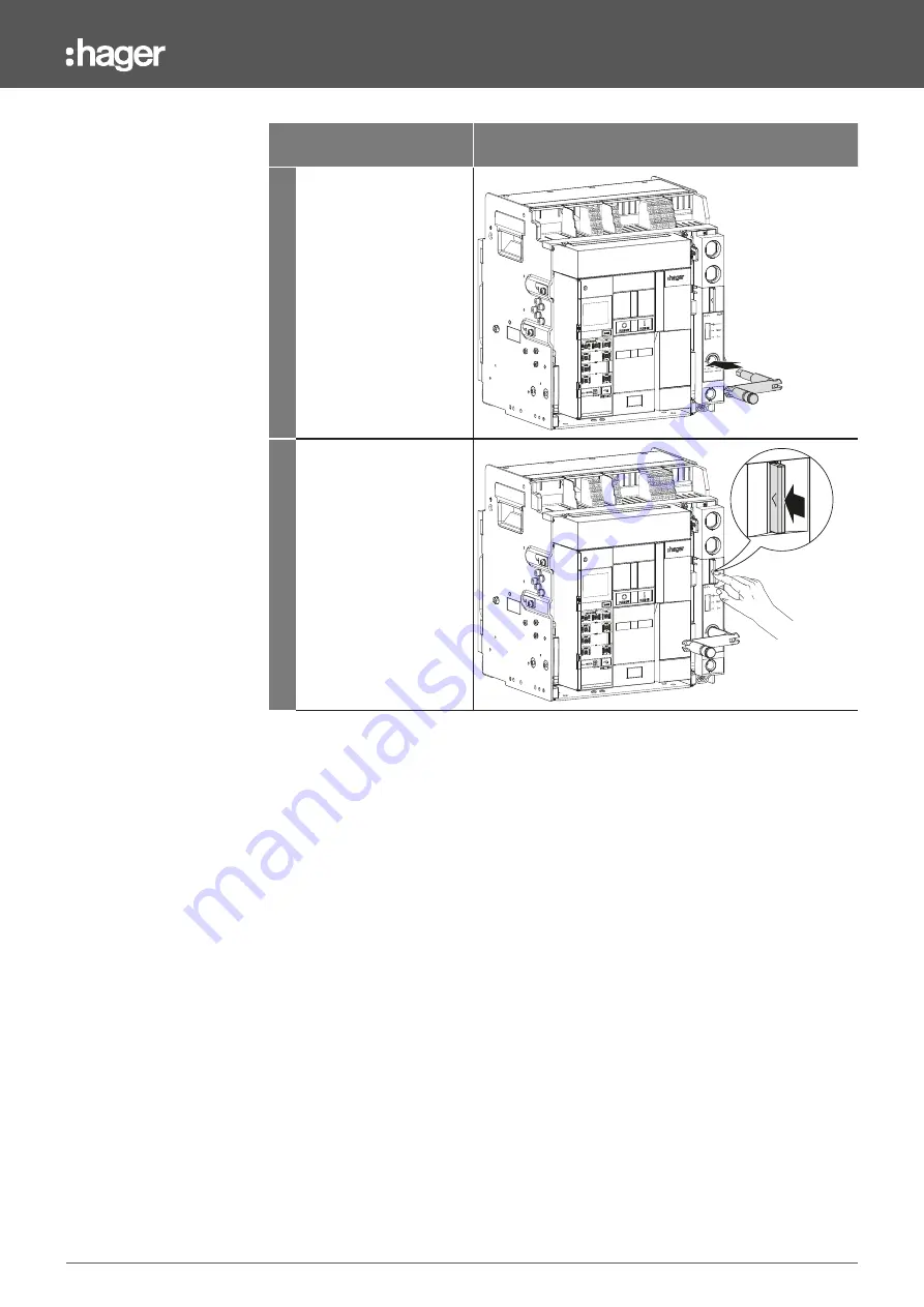
8.1 Changing from connected position to test position

Action

Illustration 

4

Insert the racking handle 
into the racking place.

5

Press the padlocking and 
position acknowledgement 
tab.

Summary of Contents for HW+ Series

Page 1: ...Installation manual hw Air circuit breakers HW1 RESET AUTO MANUAL In 16 0 0 A 5 8 MEASURES...

Page 2: ...operation 24 6 1 Description 24 6 2 Closing and opening the circuit breaker 28 07 Positions of the drawout circuit breaker in the chassis 29 08 Positions of the drawout circuit breaker in the chassis...

Page 3: ...7 Connecting the accessories and auxiliaries 99 17 8 Connection of the OAC output contacts 100 17 9 Connecting the inputs 103 17 10 Connecting the ZSI input and output contacts 104 17 11 Installation...

Page 4: ...ording to the risk level DANGER DANGER indicates an imminent dangerous situation which if not avoided will result in death or serious injuries ATTENTION ATTENTION indicates a warning message relating...

Page 5: ...ical documentation relating to them If products and components from other manufacturers are used they must be recommended or approved by Hager Appropriate use of Hager products during transport storag...

Page 6: ...ion Date 6LE007893Ad December 2023 Documents to consult Document Reference User manual for sentinel hw electronic trip units 6LE007969A User manual for sentinel Energy hw electronic trip units 6LE0081...

Page 7: ...button 3 Lifting handle 4 Opening push button 5 Closing push button 6 Terminal blocks TB 7 Charging handle 8 Circuit breaker rating label 9 Closing spring status indicator A Contact opening and closin...

Page 8: ...ng coil 8 UV undervoltage release coil or SH shunt trip coil 9 Locking the circuit breaker in open position using padlocks OLP A Locking the circuit breaker in open position using key locks OLK Z Read...

Page 9: ...5H module Or 1 connection via RJ45 cable for connection to the Modbus TCP HWY966H module External sensors 4th S1 and 4th S2 connection of an external ENCT neutral current sensor for 3 pole circuit bre...

Page 10: ...ip alarms and the remote reset of the OAC alarm output contacts with the sentinel Energy trip unit Integrated ZSI Zone selectivity function Connection to downstream circuit breakers STD1 selectivity o...

Page 11: ...f the drive mechanism Additional CC Connection of a closing coil CC Additional AX1 vN Auxiliary contact No 1 Signals the open closed status of the circuit breaker vN connection to the neutral potentia...

Page 12: ...circuit breaker open closed status 4 contacts by default 12 vN Neutral potential ENVA The cables flexible or rigid used must have a cross section between 0 6 mm and 2 5 mm In order to be properly held...

Page 13: ...CC SH UV2 UV SH2 RTC FS2 C22 C21 C23 SH2 UV2 D22 D21 F22 F24 F21 MO M1 M2 M4 AX 31 11 12 vN 14 21 22 24 32 34 41 42 44 MO CC A2 A1 SC 13 A3 CC Second possibility FS MO F11 F12 F14 C R1 R2 R4 UV D12 M...

Page 14: ...cessory connector cover 6 Charging handle 7 Circuit breaker rating label 8 Closing spring status indicator 9 Contact opening and closing indicator A Trip unit Z Transparent cover of the trip unit 1 2...

Page 15: ...e release coil or SH shunt trip coil 8 Locking the circuit breaker in open position using padlocks OLP 9 Locking the circuit breaker in open position using key locks OLK A RTC Ready to Close contact Z...

Page 16: ...handle 6 Handle 7 Handle storage space 8 Guide rail 9 PS position contacts A RI open door racking interlock Z Locking of the position of the moving part using CL key locks E MI mechanical interlock R...

Page 17: ...RJ45 cable for connection to the Modbus RTU HWY965H module Or 1 connection via RJ45 cable for connection to the Modbus TCP HWY966H module Additional The chassis of the HW1 drawout circuit breakers is...

Page 18: ...nfigured by default for remote acknowledgement of the sentinel trip unit s trip alarms and the remote reset of the OAC alarm output contacts with the sentinel Energy trip unit Integrated ZSI Zone sele...

Page 19: ...N Auxiliary contact No 1 Signals the open closed status of the circuit breaker vN connection to the neutral potential Integrated AX2 Auxiliary contact No 2 Signals the circuit breaker open closed stat...

Page 20: ...status 4 contacts by default PS Position contacts Up to 5 contacts indicating the position of the circuit breaker in the chassis 12 vN Neutral potential ENVA The cables flexible or rigid used must hav...

Page 21: ...R2 R4 UV D12 M1 M2 M4 AX PS RTC FS2 31 11 14 21 22 24 32 34 41 42 44 T11 D11 D12 D14 D21 C11 C21 D12 D22 D24 T12 T14 C12 C14 C22 C24 MO CC UV SH2 SH UV2 A2 C12 C11 D11 A1 SC C13 A3 SH CC F12 12 vN FS...

Page 22: ...l Energy electronic trip unit on the front to protect against overloads and short circuits The detailed description of the characteristics functions and settings is available in the 6LE007969A user ma...

Page 23: ...h a relative humidity of 45 to 85 max Altitude hw air circuit breakers can be used without derating up to an altitude of 2000 m Above this refer to the values provided in the Technical Catalogue 6LE00...

Page 24: ...circuit breaker has the following elements on the front 1 Charging handle 2 Closing push button 3 Closing spring status indicator 4 Contact opening and closing indicator 5 Opening push button 6 RESET...

Page 25: ...ring loaded but not ready to close because Following tripping the circuit breaker has not been reset via the acknowledgement procedure see 6LE007331A user manual for HW1 air circuit breakers Chapter 0...

Page 26: ...ss the RESET re arm button before closing the circuit breaker again after tripping This mode is usually used if the circuit breaker is remotely monitored as it can be closed without requiring a person...

Page 27: ...ircuit breaker It must be charged first and there are two procedures for this Manual charging Charge the spring using the charging handle until the status of the indicator changes Automatic charging I...

Page 28: ...cuit breaker operation 6 2 Closing and opening the circuit breaker The detailed description of the circuit breaker closing and opening operations is available in the 6LE007331A user manual for HW1 air...

Page 29: ...g and position acknowledgement tab must be pressed In 16 0 0 A RESET AUTO MANUAL 1 Padlocking and position acknowledgement tab 1 Circuit breaker position Circuit breaker status Mechanical position ind...

Page 30: ...ted by qualified personnel in accordance with to the installation standards in force in the relevant country To change from connected position to test position Action Illustration 1 Check that the cir...

Page 31: ...f the drawout circuit breaker in the chassis 8 1 Changing from connected position to test position Action Illustration 4 Insert the racking handle into the racking place 5 Press the padlocking and pos...

Page 32: ...in the chassis 8 1 Changing from connected position to test position Action Illustration 6 Turn the racking handle anti clockwise until the status indicator is displayed TEST and the padlocking and po...

Page 33: ...sition Action Illustration 1 Check that the circuit breaker is in the test position and the mechanical position indicator displays TEST 2 Press the padlocking and position acknowledgement tab 3 Turn t...

Page 34: ...2 Changing from test position to disconnected position Action Illustration 3 until the status indicator is displayed and the padlocking and position acknowledgement tab comes out of its housing Clac...

Page 35: ...operated by qualified personnel in accordance with to the installation standards in force in the relevant country To change from disconnected position to test position Action Illustration 1 Verify th...

Page 36: ...from disconnected position to test position Action Illustration 4 Press the padlocking and position acknowledgement tab 5 Turn the racking handle clockwise until the status indicator is displayed TES...

Page 37: ...tion to connected position To change from test position to connected position Action Illustration 1 Check that the circuit breaker is in the test position and the mechanical position indicator display...

Page 38: ...8 4 Changing from test position to connected position Action Illustration 3 until the status indicator is displayed and the padlocking and position acknowledgement tab comes out of its housing Clac 4...

Page 39: ...ns in the chassis in the disconnected position Pull the guide rails as far as possible while holding the upper part of the circuit breaker Clac 3 Slide the circuit breaker from the chassis on its guid...

Page 40: ...40 6LE007596Ad Extracting the drawout circuit breaker Action Illustration 4 Remove the circuit breaker from the guide rails see Chapter 14 2 Handling drawout circuit breakers...

Page 41: ...g suitable lifting equipment position the circuit breaker on the guide rails CAUTION Risk of the circuit breaker falling out Risk of injury by crushing Before handling the circuit breaker ensure the c...

Page 42: ...ing the drawout circuit breaker Action Illustration 4 Remove the lifting equipment 5 Push the circuit breaker to the back of the chassis without pushing on the guide rails 6 Push the guide rails to th...

Page 43: ...pallet truck to move the hw transport box Store the circuit breaker in its original transport box indoors only At a temperature between 40 C and 70 C In an environment as described in chapter Circuit...

Page 44: ...44 6LE007596Ad Storage Do not store more than two circuit breakers in their original packaging one on top of the other...

Page 45: ...ed circuit breaker Packaging 3 1 2 1 HW1 air circuit breakers can be identified by means of the various labels affixed to the product or packaging ATTENTION For more information on the codification an...

Page 46: ...ion 3 List of accessories mounted 4 Configuration identifier HWY045H FC UP HWY045H FC DWN HWX004H MO 250V AC HWX060H CC 200 250V AC HWX023H SH SH1 UV2 200 250V AC HWX033H UV UV1 SH2 200 250V AC HWX040...

Page 47: ...ted insulation voltage 7 Uimp Rated impulse withstand voltage 8 Category 9 Frequency A Manufacturing date code Z Standards E QR code to access the documentation online R Symbol of a circuit breaker su...

Page 48: ...packaging 1 2 3 Hager Electro SAS BP3 67215 OBERNAI CEDEX FRANCE HW1M416DB 6 HWX023H SH 200 250V AC HWX033H UV 200 250V AC HWX028H CLOSING COIL 200 250V AC HWX040H SWITCH AX HWX090H OAC HWW451H OCR S...

Page 49: ...m its case following the procedure below Action Illustration 1 Remove the 6 screws 3 on each side which hold the case on the pallet 2 Remove the case using the side handles 3 Remove the adhesive tape...

Page 50: ...0 6LE007596Ad Unboxing 13 2 Fixed circuit breaker To remove a fixed circuit breaker from its pallet proceed as follows Action Illustration 1 Remove the 6 screws holding the circuit breaker in place PH...

Page 51: ...Changing from the connected position to the test position and 8 2 Changing from the test position to the disconnected position 2 Pull the guide rails as far as possible 3 Slide the circuit breaker fr...

Page 52: ...lustration 4 Remove the circuit breaker from the guide rails using an appropriate lifting device 5 Remove the 4 screws attaching the chassis to the brackets 6 Remove the chassis from the pallet using...

Page 53: ...d circuit breaker drawout circuit breaker and chassis have lifting handles to be used for handling Ensure you have a lifting system corresponding to the weight of the circuit breaker or chassis to be...

Page 54: ...cuit breakers 14 1 Handling fixed circuit breaker Use the lifting handles on the side of the circuit breaker It is recommended that the circuit breaker be handled by 2 persons or that a lifting system...

Page 55: ...ove the two elements separately ATTENTION Risk of the circuit breaker falling out Risk of injury by crushing To handle circuit breakers wear suitable personal protective equipment PPE Handling the cha...

Page 56: ...2 Handling drawout circuit breakers Handling the circuit breaker Use the lifting handles on the side of the circuit breaker It is recommended that the circuit breaker be handled by 2 persons or that...

Page 57: ...tall an HW1 circuit breaker comply with the following dimensions for mounting 3 poles Fixed version REP 15 15 276 60 5 125 250 13 13 216 6 5 6 5 25 45 37 4 13 13 6 5 6 5 6 5 190 43 43 70 70 55 55 250...

Page 58: ...ons 15 1 Circuit breaker dimensions 4 poles Fixed version 15 15 346 60 5 125 320 13 13 216 6 5 6 5 25 45 37 4 13 13 6 5 6 5 6 5 190 43 113 70 70 55 55 320 17 7 312 1 253 4 9 85 15 44 25 11 137 4 41 1...

Page 59: ...ening dimensions 15 1 Circuit breaker dimensions 3 poles Drawout version 29 18 5 48 150 228 90 70 70 85 1 283 1 267 5 321 5 253 1 199 58 280 231 216 46 49 25 11 44 15 15 51 5 Test position Disconnecte...

Page 60: ...60 6LE007596Ad Fastening dimensions 15 1 Circuit breaker dimensions Chassis mounting Bottom view Rear view 17 100 25 75 6 7 180 73 150 218 6 5...

Page 61: ...ing dimensions 15 1 Circuit breaker dimensions 4 poles Drawout version 90 70 70 85 2 348 8 269 53 6 280 231 216 46 49 70 29 18 5 48 150 228 267 5 321 5 253 1 15 15 25 11 44 51 5 Test position Disconne...

Page 62: ...62 6LE007596Ad Fastening dimensions 15 1 Circuit breaker dimensions Chassis mounting Bottom view Rear view 73 150 288 6 5 17 100 25 75 6 7 250...

Page 63: ...he following connection dimensions Rear horizontal RC connections For fixed or drawout 3 pole or 4 pole version 44 45 25 44 44 44 25 25 25 45 45 15 15 150 11 70 70 70 Rear view Side view The dimension...

Page 64: ...al RC connections With SP spreaders for fixed or drawout 3 pole circuit breakers The dimensions given are valid for the fixed and drawout versions Rear view Side view 11 77 77 77 25 25 25 25 25 25 45...

Page 65: ...for fixed or drawout 4 pole circuit breakers The illustration above shows a drawout version The dimensions given are valid for the fixed and drawout versions Rear view Side view Top view 77 45 25 25...

Page 66: ...istribution board for fixed or drawout 3 pole or 4 pole circuit breaker The illustration above shows a drawout version The dimensions given are valid for the fixed and drawout versions Rear view Side...

Page 67: ...nnections Rear vertical RC connections For fixed or drawout 3 pole or 4 pole version The dimensions given are valid for the fixed and drawout versions Rear view Side view Top view 70 70 25 11 44 44 25...

Page 68: ...tical RC connections Long for UNIMES type distribution board for fixed or drawout 3 pole or 4 pole circuit breaker The dimensions given are valid for the fixed and drawout versions Rear view Side view...

Page 69: ...astening dimensions 15 2 Circuit breaker connections FC front connections Front connections for fixed 3 pole or 4 pole circuit breaker Rear view Side view 12 150 27 5 300 44 45 25 44 44 44 25 25 25 45...

Page 70: ...E007596Ad Fastening dimensions 15 2 Circuit breaker connections FC front connections For drawout 3 pole or 4 pole circuit breaker Rear view Side view 150 342 44 45 25 44 44 44 25 25 25 45 45 11 70 70...

Page 71: ...sions 15 2 Circuit breaker connections FC front connections For drawout 3 pole or 4 pole circuit breaker with short terminal extensions in bottom position Rear view Side view 150 311 44 45 25 44 44 44...

Page 72: ...596Ad Fastening dimensions 15 2 Circuit breaker connections FC front connections with SP spreaders For fixed 3 pole circuit breaker Rear view Side view 77 77 77 25 25 25 25 25 25 45 45 52 403 150 11 1...

Page 73: ...reaker connections FC front connections with SP spreaders For fixed 4 pole circuit breaker Rear view Side view 403 150 12 15 42 5 77 45 25 25 77 77 77 25 25 25 25 25 25 45 45 52 11 403 150 12 15 42 5...

Page 74: ...96Ad Fastening dimensions 15 2 Circuit breaker connections FC front connections with SP spreaders For drawout 3 pole circuit breaker Rear view Side view 150 15 77 77 77 25 25 25 25 25 25 45 45 52 11 4...

Page 75: ...astening dimensions 15 2 Circuit breaker connections FC front connections with SP spreaders For drawout 4 pole circuit breaker Rear view Side view 77 45 25 25 77 77 77 25 25 25 25 25 25 45 45 52 11 15...

Page 76: ...15 2 Circuit breaker connections FC front connections with SP spreaders For drawout 3 pole circuit breaker with short terminal extensions in bottom position Rear view Side view 150 15 77 77 77 25 25...

Page 77: ...Circuit breaker connections FC front connections with SP spreaders For drawout 4 pole circuit breaker with short terminal extensions in bottom position Rear view Side view 77 45 25 25 77 77 77 25 25 2...

Page 78: ...ning dimensions 15 2 Circuit breaker connections FC front connections with VCA vertical connectors In front for fixed 3 or 4 pole circuit breaker Rear view Side view 70 70 442 70 15 15 15 15 150 25 11...

Page 79: ...ning dimensions 15 2 Circuit breaker connections FC front connections with VCA vertical connectors At rear for fixed 3 or 4 pole circuit breaker Rear view Side view 70 70 442 70 15 15 15 15 150 25 11...

Page 80: ...ing dimensions 15 2 Circuit breaker connections FC front connections with VCA vertical connectors In front for drawout 3 pole or 4 pole circuit breaker Rear view Side view 70 70 484 70 15 15 15 15 150...

Page 81: ...astening dimensions 15 2 Circuit breaker connections FC front connections with VCA vertical connectors At rear for drawout 3 or 4 pole circuit breaker Rear view Side view 70 70 484 70 15 15 15 15 150...

Page 82: ...eaker and the distribution board door The reference point is one of the product s fastening holes Fixed 3 and 4 pole circuit breaker fastening on a plate or mounting rails Fixed 3 and 4 pole circuit b...

Page 83: ...d Fastening dimensions 15 3 DF door frame cut out Comply with the following dimensions to install a door frame Fixed 3 pole circuit breaker Fixed 4 pole circuit breaker 83 85 144 35 125 60 5 83 85 144...

Page 84: ...84 6LE007596Ad Fastening dimensions 15 3 DF door frame cut out Drawout 3 pole circuit breaker Drawout 4 pole circuit breaker 144 7 90 144 7 90...

Page 85: ...85 6LE007596Ad Fastening dimensions 15 3 DF door frame cut out DF Door Frame Align the centre A of the circuit breaker with the centre A of the door frame 301 5 311 05 183 7...

Page 86: ...4 Cut out of the HTD210H panel display Comply with the following dimensions to install an HTD210H panel display 97 97 92 92 27 8 18 Dimensions Width mm Height mm Depth mm HTD210H 97 97 18 45 with fas...

Page 87: ...ted by qualified personnel in accordance with to the installation standards in force in the relevant country To ensure the safety of people and the installation comply with the following safety cleara...

Page 88: ...disconnected position DANGER Risk of electric shock electrocution or electric arc Danger to life risk of injury due to electric shock or risk of serious injury Ensure that the device is only installed...

Page 89: ...er on a plate with sufficient resistance or on mounting supports that are stable enough 2 Identify at least 4 mounting holes 2 on each side complying with the following dimensions 3 poles 75 100 250 T...

Page 90: ...ni 6 5 mm 4 Mount the circuit breaker using M6 screws 13 Nm 10 5 If the mounting plate is not connected to the earth connect an earthing conductor to each side of the mounting plate using an M6 screw...

Page 91: ...ing with the following dimensions The circuit breaker must always be fastened by at least four screws 62 A 62 99 5 44 106 12 6 5 C 100 125 B 125 56 3P 4P A mm 99 5 169 5 B mm 100 170 C mm 125 195 2 Dr...

Page 92: ...unt the circuit breaker using M6 screws 13 Nm 17 4 If the panel is not earthed connect an earthing cable to each side mounting plate using an M6 screw and an unused hole It is recommended that an eart...

Page 93: ...ction Illustration 1 The circuit breaker must first be removed from the chassis Be sure to mount the circuit breaker on a plate with sufficient resistance or on mounting supports that are stable enoug...

Page 94: ...d 4 poles 75 100 250 3 Drill the 4 fixing holes mini 6 5 mm 4 Mount the chassis using M6 screws 13 Nm 10 5 If the plate is not earthed connect an earthing conductor directly to the chassis using an M1...

Page 95: ...ched to the electrical distribution board not directly on the rear sockets If a short circuit occurs the deformation of the connecting bars must not damage the fastening of the rear connections To gua...

Page 96: ...Cable retaining bars are indicated for this If necessary extend the rear sockets using terminal extensions for cables then connect them to the connection cables ATTENTION Hager does not provide either...

Page 97: ...y accessories designed to strengthen the isolation between the phases at the rear connections 1 IB interphase barrier ATTENTION The use of interphase barriers is mandatory for supply voltages over 500...

Page 98: ...and raised the protection class to IP30 It is used for a fixed or drawout circuit breaker For a drawout circuit breaker the IP30 protection level is guaranteed in the connected position and in the tes...

Page 99: ...6LE007543A Terminal blocks TB The terminal blocks TB are used to connect to the various circuit breaker accessories and auxiliary devices For a pre configured circuit breaker all the accessories inclu...

Page 100: ...ntinel trip unit LTD trips on one output STD INST MCR on one output and GF on one output overload pre alarm HWF trip with the sentinel Energy trip unit LTD trip grouped alarm configured on Short Time...

Page 101: ...tact DO4 open closed Tripping due to a critical system alarm Contact No Not active Active HWF output contact DO5 open closed common LTD GF STD INST MCR DO1 DO2 PTA HWF DOC DO3 DO4 DO5 OAC ATTENTION Th...

Page 102: ...102 6LE007596Ad Installation 17 8 Connection of the OAC output contacts In 16 0 0 A RESET AUTO MANUAL Fixed circuit breaker In 16 0 0 A RESET AUTO MANUAL Drawout circuit breaker...

Page 103: ...R DI digital input is used to remotely acknowledge the sentinel trip unit s trip pop ups and remotely reset the OAC alarm output contacts It can be used for one of the following control functions on t...

Page 104: ...fault trips without waiting till the end of its time delay hw circuit breakers can be linked with h3 Energy circuit breakers For zone selectivity to work correctly the ZSI hw circuit breakers and the...

Page 105: ...ctivity on the earth fault protection Cmn2 common hw air circuit breakers have 6 ZSI terminal blocks enabling the upstream or downstream circuit breakers to be connected to deploy zone selectivity ZSI...

Page 106: ...es refer to the following manuals Accessories Instructions Coils 6LE007405A MO charging Motor 6LE007406A Coils Three types of coils can be installed in the dedicated positions behind the front cover o...

Page 107: ...ration Cycle Counter 6LE007487A OAC Output Alarm Contact module 6LE007430A FS Fault trip contact 6LE007676A PS Position contact This contact indicates the connected test or disconnected position of th...

Page 108: ...alling accessories CYC Operation Cycle Counter The cycle counter shows the number of ON OFF operations completed by the circuit breaker RTC Ready to Close contact The ready to close contact gives the...

Page 109: ...module has 5 digital output contacts allowing alarm trip or operating events to be signalled For more information see chapter 17 8 Connecting the output contacts FS Fault trip contact The trip unit s...

Page 110: ...N earthing system It is installed on the neutral distribution bar generally located on the left of the circuit breaker It must be connected to the terminals marked ESP 4th S1 black wire and 4th S2 red...

Page 111: ...play 6LE002999A Communication module The HW1 circuit breaker equipped with a sentinel Energy trip unit can be connected to a Modbus communication network via a Modbus RTU communication module or a Mod...

Page 112: ...ation via modbus if a communication module is installed or from Hager Power setup USB C This insulation module also prevents the overvoltage caused by the SH or CC coil affecting the trip unit ATTENTI...

Page 113: ...connection to the terminals CIP 1 and CIP 2 ATTENTION An external 24 V DC SELV power supply recommended reference HTG911H must be connected to the TU terminal of the circuit breaker and the HWY210H ad...

Page 114: ...er open closed status 4 contacts by default 12 vN Neutral potential ENVA The cables flexible or rigid used must have a cross section between 0 6 mm and 2 5 mm In order to be properly held in place in...

Page 115: ...SH2 RTC FS2 C22 C21 C23 SH2 UV2 D22 D21 F22 F24 F21 MO M1 M2 M4 AX 31 11 12 vN 14 21 22 24 32 34 41 42 44 MO CC A2 A1 SC 13 A3 CC Second possibility FS MO F11 F12 F14 C R1 R2 R4 UV D12 M1 M2 M4 AX 31...

Page 116: ...cts by default PS Position contacts Up to 5 contacts indicating the position of the circuit breaker in the chassis 12 vN Neutral potential ENVA The cables flexible or rigid used must have a cross sect...

Page 117: ...1 M2 M4 AX PS RTC FS2 31 11 14 21 22 24 32 34 41 42 44 T11 D11 D12 D14 D21 C11 C21 D12 D22 D24 T12 T14 C12 C14 C22 C24 MO CC UV SH2 SH UV2 A2 C12 C11 D11 A1 SC C13 A3 SH CC F12 12 vN FS MO F11 F14 C M...

Page 118: ...LTD Long time delay protection setting 2 STD Short Time Delay protection setting 3 INST Instantaneous protection setting 4 GF earth fault protection setting 5 N neutral protection setting adjustment 1...

Page 119: ...f injury due to electric shock or risk of serious injury Ensure that the device is only commissioned by qualified personnel who are equipped with adequate safety equipment ATTENTION For any further in...

Page 120: ...s of the main circuit in the chassis when the circuit breaker is in the disconnected or test position In this way it precludes accidental access to the connections The high and low shutters work indep...

Page 121: ...nding chassis It is composed of screws and pins which must be installed on the chassis and circuit breaker in one of the following 10 combinations The combination chosen on the chassis must correspond...

Page 122: ...1 3 Mechanical interlock Refer to 6LE007624A and 6LE008138A manual for installation of this locking accessory The interlocking kit is used to interlock 2 circuit breakers installed vertically or horiz...

Page 123: ...123 6LE007596Ad Notes...

Page 124: ...6LE007893Ad Hager Electro SAS 132 Boulevard d Europe BP3 67210 OBERNAI CEDEX www hager com 2024 04...

Reviews: