background image

52

Technical changes reserved

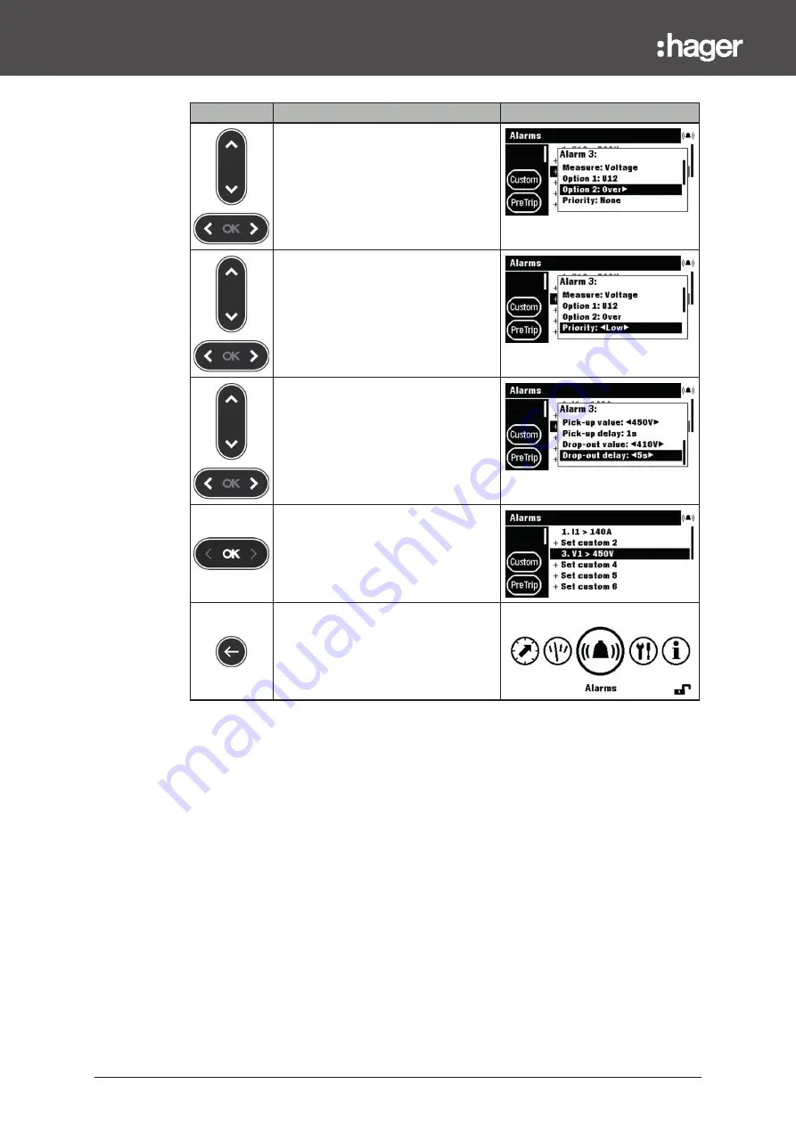
Alarms menu

Key

Step/Action

Screen

8.

Select and set the alarm activation 

condition (Option 2).

9.

Select and set the alarm priority.

10. Select and set activation thresholds 

and time delays:


- threshold: Pick-up value


- threshold: Drop-out value


- time delay: Pick-up delay


- time delay: Drop-out delay

11. Confi m the settings.


- The new custom alarm is set.

12. Return to the Alarms menu.

Summary of Contents for h3+ HTD210H

Page 1: ......

Page 2: ......

Page 3: ...ly 21 3 3 First power up 24 4 Display modes and navigation 25 4 1 Navigation 25 4 2 Start up screen 27 4 3 Live mode 28 4 4 Main menu 30 4 5 Locked Unlocked mode 32 4 6 Alarm warnings 34 5 Protection...

Page 4: ...hanges reserved 9 Information menu 65 9 1 Submenus 65 9 2 Navigation in submenu MCCB information 66 9 3 Navigation in History of alarm events and History of trip events 67 9 4 Submenus contents 68 10...

Page 5: ...an imminently hazardous situation which if not avoided will re sult in death or serious injury WARNING WARNING indicates a potentially hazardous situation which if not avoided could result in death o...

Page 6: ...ions described in the catalogue and in the relevant technical documentation If products and components from other manufacturers are used these must be recommended or approved by Hager Proper transport...

Page 7: ...arately from household waste According to local laws and regulations your Panel display product shall be disposed of separately from household waste When this product reaches its end of life take it t...

Page 8: ...8 Technical changes reserved...

Page 9: ...ed in clearly arranged tables Key Step Action Screen Touch key 1 Procedural instruction step 1 Result of first action Display view Touch key 2 Procedural instruction step 2 Result of second action Dis...

Page 10: ...ion 6LE002194A h3 Moulded Case Circuit Breakers up to 250 A Technical catalogue 6LE005047A h3 Communication System manual 6LE002998A HTP610H h3 Configuration tool user manual 6LE003137A Contact Addres...

Page 11: ...at a panel where the connected Energy MCCB is installed Various adaptors each with a certain cable length allow the HTD210H Panel display to be mounted within easy reach of the observer For example s...

Page 12: ...on the displayed menu 5 left OK right key Left and right navigation between menus OK Confirming entries Enter 6 back key One step back or exit the current menu By holding the key the display changes t...

Page 13: ...enu Main Menu Alarm pop up Live mode Menu e g Measure Standby function By default the backlight of the display is always on It can be deactivated in the Configuration menu If the standby function is a...

Page 14: ...viour Alarm with medium and high priority red blinking Communicating with the Energy MCCB yellow blinking The device is supplied with power and is ready green External ports External port Description...

Page 15: ...isation of all measurements Setting the representation of the measurements Protection Management of the Protection settings Alarms Management of alarms Custom PreTrip Trip OAC Configuration Setting th...

Page 16: ...eristics Operating temperature range 10 C 55 C Storage temperature 20 C 70 C Degree of pollution 2 Installation category III IP rating of front side IP65 IP rating of back side IP20 Mechanical protect...

Page 17: ...Technical changes reserved 17 The HTD210H Panel display 2 4 Dimensions and cut outs Dimensions Width mm Height mm Depth mm HTD210H 97 97 18 45 Panel cut out 92 92 up to 8...

Page 18: ...daptor for h3 3 COM module Modbus RTU h3 without I O Reference Description Length m HTC140H CIP 24 V Adaptor 1 2 HTC310H COM module Modbus RTU h3 without I O HTC320H COM module Modbus RTU h3 with I O...

Page 19: ...ic shock or risk of serious injury Make sure that the device is installed only by a qualified electrician according to the installation standards in force in the country NOTICE Risk of damaging the HT...

Page 20: ...e MCCB can only be opened in the OFF or tripped position 2 Open the front cover of the Energy MCCB 3 Insert the CIP connector of the CIP Adaptor into the CIP socket NOTICE Risk of damaging plug and so...

Page 21: ...y via the HTC3XXH CIP Adaptor Various adaptors each with a certain cable length allow the HTD210H Panel display to be mounted within easy reach of the observer For example several units can be mounted...

Page 22: ...B Step Action 1 Make sure the COM module is connected to the MCCB If not insert the CIP connector of the second CIP Adaptor into the free CIP socket NOTICE Risk of damaging plug and socket Observe the...

Page 23: ...aptor to connect with power supply 6 CIP Aadaptor to connect with Panel display 3 CIP Adaptor to connect with power supply 7 Energy MCCB 4 Power supply HTG911H Step Action 1 Insert the connector of th...

Page 24: ...preset If this is appropriate confirm with the OK key Changing the language Key Step Action Screen 1 Select another language 2 Confirm the selection The selected language will appear on the display Th...

Page 25: ...identical within all menus 1 Submenus 2 Padlock symbol Menu is protected 3 Name of menu 4 Icon of menu 5 Data window Submenus Each icon refers to a submenu The activated submenu is highlighted To sel...

Page 26: ...he displayed menu left OK right Left and right navigation within menus and submenus OK Confirming entries Enter Back One step back Hold the key to exit the current menu and enter Live mode up down Up...

Page 27: ...layed the Panel display is fetching its configuration settings stored in the Energy MCCB If the stored data is corrupted or empty e g on first power up default values will be set After the successful...

Page 28: ...en views set as favourites in the Measure menu To set the favourites refer to Setting favourites and representation on page 44 The display shows each value for about 3 seconds and then scrolls to the...

Page 29: ...NOTE The representation chosen in the Live mode menu is automatically applied to the concerned screen view in the Measure menu Navigation in Live mode Key Navigation Pause and start the live animatio...

Page 30: ...laying the protection settings Measure Displaying the available measurements Setting favourites Alarms Changing and displaying the available alarms Configuration Changing and displaying device setting...

Page 31: ...modes and navigation Opening the Main menu from Live mode Key Step Action Screen or 1 Stop Live mode The Main menu opens with the Measure menu preselected Selecting and opening a menu Key Step Action...

Page 32: ...unlocked and no more password protected Locked blinking Selected menu or function is password protected Enter the password to unlock the function Locked Menus The following menus are locked by default...

Page 33: ...n menu The closed lock symbolizes that the display is locked 2 Open the password input menu The password consist of 4 digits 3 Increase decrease the value of the digits 4 Select the next digit and set...

Page 34: ...h x x x x Stored in active alarms list In Live mode only an alarm icon is displayed above the Contextual key as a contextual icon If no alarm pop up is displayed the alarm can be recalled by touching...

Page 35: ...Occurs when the load current of the circuit breaker has reached the defined Threshold default 90 Ir Trip test Has occurred on the 06 03 2018 at 14 35 a trip test was performed via the h3 Configuratio...

Page 36: ...ual key High priority level active alarm pop ups can be recalled after having been acknowledged using the Contextual key when the alarm icon is displayed Active alarms with medium priority level can b...

Page 37: ...ttings is protected by a password refer to Locked Unlocked mode on page 32 As long as the menu is locked the settings are protected against unauthorised changes Available submenus Submenus Attribute L...

Page 38: ...bmenu is highlighted The adjustable parameters are displayed in the Data window 3 Confirm the selection The first parameter in the Data window is highlighted 4 Select a parameter The selected paramete...

Page 39: ...n N IN Ir Ir 50 100 Off to be kept at Off for 3P circuit breakers Attribute Parameter Unit Description G Ground Off 3P 4P default enabled if disabled Ig tg and I2t ground will be hidden Ig x In Range...

Page 40: ...40 Technical changes reserved...

Page 41: ...TE The representation of the individual measured values value bar graph or gauge depends on the favourite settings made in the Measure menu or on the representation view in Live mode Easy navigation T...

Page 42: ...l Functions Current measurements Phase to phase voltage measurements Phase to neutral voltage measurements Active power Reactive power Apparent power and maximum values On demand measurements Power fa...

Page 43: ...bmenu is done horizontally to select a labelled screen view Each submenu has several labelled screen views except the F submenu with only one screen view 1 Submenus The selected submenu icon is highli...

Page 44: ...reen 1 Open the Measure menu 2 Select a submenu The selected submenu icon is highlighted 3 Select the desired screen view The selected screen view label is highlighted The screen view status is displa...

Page 45: ...Step Action Screen 1 Open the Measure menu 2 Select a submenu The selected submenu icon is highlighted 3 Select the desired screen view The selected screen view label is highlighted 4 Open the Settin...

Page 46: ...m rms value of the calculated current Ig can be reset Unb Max Last Maximum of unbalanced current can be reset Voltage Phase to phase inst max unb avg V U12 rms phase 1 to phase 2 voltage V U23 rms pha...

Page 47: ...3 Phase reactive power kvar Qtot Total reactive power kVA S1 S2 S3 Phase apparent power kVA Stot Total apparent power kW P1 P2 P3 Phase active power can be reset kW Ptot Total active power can be rese...

Page 48: ...of U12 U23 THD of U23 U31 THD of U31 V1N THD of V1N V2N THD of V2N V3N THD of V3N I1 THD of I1 I2 THD of I2 I3 THD of I3 IMax Maximum THD between I1 I2 and I3 Energy Ea Er Es kWh Ealn Direct active e...

Page 49: ...rms menu Setting and editing alarms will be explained 7 1 Submenus In the Alarms menu the following parameters can be set and modified Custom alarms Pre trip alarm Trip alarms OAC output contact The m...

Page 50: ...up is displayed on the Panel display Its threshold can be modified in the PreTrip submenu Trip alarm There are 5 kinds of Trip alarms corresponding to the following trip events Long time trip L Short...

Page 51: ...fined custom alarms are displayed 3 Confirm the selection The first parameter of the custom alarms list is highlighted 4 Select the desired custom alarm to display or to modify the settings 5 Confirm...

Page 52: ...ation condition Option 2 9 Select and set the alarm priority 10 Select and set activation thresholds and time delays threshold Pick up value threshold Drop out value time delay Pick up delay time dela...

Page 53: ...ed The adjustable parameters are displayed in the Data window 3 Confirm the selection The threshold parameter is highlighted 4 Confirm the selection of the threshold parameter The threshold pop up is...

Page 54: ...54 Technical changes reserved Alarms menu Key Step Action Screen 10 Confirm the Pre trip alarm delay The new parameters for the alarm type are set 11 Return to the Alarms menu...

Page 55: ...ghted The adjustable parameters are displayed in the Data window 3 Confirm the selection The first parameter is highlighted 4 Select the parameter to be modified 5 Confirm the selection The alarm sett...

Page 56: ...ghted 4 Confirm the selection of the Assignment parameter The Assignment pop up is displayed 5 Select the alarm to be assigned to the OAC output contact 6 Confirm the setting The alarm selected is ass...

Page 57: ...2 3 1 3 2 Lead or Lag Lead Lag NOTE If a custom alarm is defined and set to None priority the alarm is created but remains deactivated as long as its priority is set to None For more explanations on m...

Page 58: ...erved Alarms menu Assigments to Alarm types Alarm type Assignment None Pre trip alarm PTA PreTrip alarm Ir System alarm Overtemperature Neutral breach Internal error Custom alarm Custom alarm 1 Custom...

Page 59: ...of the Configuration menu and the adjustable param eters of the connected Energy MCCB 8 1 Submenus In the Configuration menu all settings are displayed and can be set excepting the protection settings...

Page 60: ...erved Configuration menu Available submenus Submenus Function Setting the Display Setting date and time Changing the password Setting the measurements Resetting min max measurements Erasing custom ala...

Page 61: ...n 1 Open the Configuration menu 2 Select a submenu The selected submenu is highlighted 3 Confirm your selection The first parameter that can be adjusted is highlighted 4 Select a parameter The selecte...

Page 62: ...e actual time HH MM Change password Parameter Description Format Change password Changing the current password 4 digits Measurement settings Parameter Description Values Phase sequence Defining the se...

Page 63: ...ues only Reset THD min max Resetting Total harmonic distortion min max values only Reset on demand P max Resetting on demand power min max values only Reset energies Resetting all energies Erasing ala...

Page 64: ...64 Technical changes reserved...

Page 65: ...n menu displays several information about the status of the connected Energy MCCB and the HTD210H Panel display itself In this menu no user inputs or settings are possible Only information is displaye...

Page 66: ...erved Information menu 9 2 Navigation in submenu MCCB information Key Step Action Screen 1 Open the Information menu 2 Scroll up and down to view more entries and their information or status 3 Return...

Page 67: ...elect the History of alarm event submenu or the History of trip events submenu The selected submenu is highlighted e g the history of trip events 3 Confirm your selection The first entry in the Data w...

Page 68: ...he circuit breaker AL status Used only if the AX AL Energy accessory is mounted ON circuit breaker is tripped OFF circuit breaker is not tripped AX counter Used only if the AX AL Energy accessory is m...

Page 69: ...ed as defective replace the MCCB Refer to your Hager contact Blinking OFF ON Check the CIP Adaptor between display and MCCB by replacing it Re connect the Panel display Refer to your Hager contact if...

Page 70: ......

Reviews: