background image

for use with the cooking appliance and 

listed in the manufacturer’s instruc-

tions should be used as suitable pro-

tection for the counter top incorpora-

ted in the appliance. Use of unsuitable 

protectors may cause accidents.

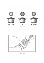
-  When the hob is in use keep all mag-

netizable objects away (credit cards, 

floppy disks, calculators and so on). 

-  After cooking is finished, switch off 

using the control provided (turn down 

to “0”), and do not rely on the pan sen-

sor.

- WARNING: Accessible parts will beco-

me hot when in use. To avoid burns and 

scalds children should be kept away.

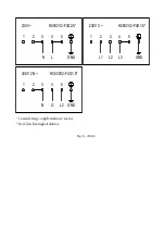
Insert in the fixed wiring a mean for 

disconnection from the supply mains 

having a contact separation in all poles 

that provide full disconnection under 

overvoltage category III conditions, in 

accordance with the wiring rules. The 

plug or omnipolar switch must be easily 

reached on the installed equipment. 

This appliance is not intended to be used 

via an external timer or a remote control 

system. 

The manufacturers decline any respon-

sibility in the event of non-compliance 

with what is described above and the 

accident prevention norms not being 

respected and followed. 

To avoid all risk, if the power cable beco-

mes damaged, it must only be replaced 

by the manufacturer, by an authorised 

service centre, or by a qualified electri-

cian. 

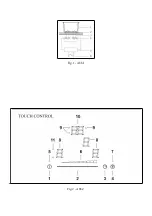
OPERATING PRINCIPLE (Fig. 1) 

It exploits the electromagnetic properties of most cooking 

vessels.

The coil (inductor) which produces the electromagnetic field is 

operated and controlled by the electronic circuit. 

The heat is transmitted to food by the cooking vessel itself. 

The cooking process takes place as described below. 

-  loss of heat is minimum (high efficiency) 

-  the system stops automatically when the vessel is removed or 

even just lifted from the hob 

-  the electronic circuit guarantees maximum flexibility and fine 

adjustments. 

(Fig. 1) 

1 Vessel 

2 Induced current 

3 Magnetic field 

4 Inductor 

5 Electronic circuit 

6 Power supply 

User’s Instructions (Fig. 2) 

1 Power ON / Po wer O FF

2 Slider sensor

3 Double / Triple Circuit

4 Lock function

5 ON/OFF LED

6 Slider LED

7 Lock LED

8 Heating zone and setting display

9 Timer indicator zone

10 Timer

11 Double / Triple Circuit LED
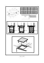
Installation 

All operations relative to installation (electric connection) should 

be carried out by skilled personnel in conformity with the rules 

in force. 

As for the specific instructions see part pertaining to installer.

Functionality Slider TC:


Slider: sensor technology of the novel Slider TC a llow s as w ell 

an adjustment of the cooking levels (1 – 9) as the tim er value (1-

99 ) by touching and pulling the finger over the designated area. 

Pulling to the right is increasing and to the left is decreasing 

accordant value.

Moreover  a  direct  selection  of  the designated value is  also 

possible on the slider area.


ON/OFF Touch Control

After connecting  to the mains the TC unit takes 1 second to 

prepare for operation. After a reset all displays and LEDs flashes 

up  for 1 second.  Af ter 1 second all displays and LEDs are 

switched off again.

The TC unit may now be switched ON by pressing the ON/OFF 

key (1). Displays show a steady “0“. Possible optic warnings 

Summary of Contents for HC-M773A

Page 1: ...EN DE HC M773A 536 01 705 ...

Page 2: ......

Page 3: ... spoons and lids on the hob surface as they will heat up When cooking in a non stick pan wi thout seasoning do not exceed 1 2 mi nutes pre heating time When cooking food that may easily stick start at a low power output level and then slowly increase while regu larly stirring If the surface of the hob is damaged immediately disconnect the appliance from the mains to prevent the possibi lity of ele...

Page 4: ...rated and controlled by the electronic circuit The heat is transmitted to food by the cooking vessel itself The cooking process takes place as described below loss of heat is minimum high efficiency the system stops automatically when the vessel is removed or even just lifted from the hob the electronic circuit guarantees maximum flexibility and fine adjustments Fig 1 1 Vessel 2 Induced current 3 ...

Page 5: ...ction all the cooking zones are able to receive a power supply above the nominal power the number of zones with booster at the same time will depend on the power provided to the different zones which must always be less than the maximum power of the hob The booster activation time is limited to 5 minutes to protect cooking utensils After the booster has automatically switched off the cooking zone ...

Page 6: ...akes place and thereafter the adjustment of the second digit In case of an active timer display the timer value may be set to 0 directly by pressing 0 on the slider area left side Switching off an active timer A timer can be switched of by setting its value to 0 A stand alone timer can be switched of by a double actuation of the power key 1 Timer Stand Alone If the control unit is switched on all ...

Page 7: ...hemical detergents such as oven sprays and spot removers Installer s Instructions Installation These Instructions are for the qualified technician as a guide to installation adjustment and maintenance according to the laws and standards in force These operations must always be carried out when the appliance has been disconnected from the electric system Positioning Fig 5 The fixture is especially ...

Page 8: ...n Niemals Aluminiumfolie benutzen oder in Aluminium verpackte Produkte di rekt auf die Fläche legen keine Me tallgegenstände wie Messer Gabeln Löffel und Deckel auf die Kochflache legen damit sie nicht heiß werden Beim Kochen mit Töpfen mit Antihaft beschichtung ohne Zugabe von Fett ist die eventuelle Vorwärmzeit auf eine oder zwei Minuten zu beschränken Das Kochen von zum Ansetzen neigen den Lebe...

Page 9: ...etriebs sind magneti sierbare Gegenstände wie Kreditkar ten Disketten Taschenrechner usw Fern zu halten Nach dem Gebrauch über die vorgese hene Vorrichtung ausschalten Vermin derung bis auf 0 ohne sich auf den Topfsensor zu verlassen Installieren Sie in der festen Verkabelung eine Abschaltvorrichtung mit omnipo larem Trennschalter der im Falle einer Überspannung der Kategorie III eine vollständige...

Page 10: ...us 0 5 Sek an Die Elektronik bleibt 20 Sekunden lang aktiviert Wird in dieser Zeit keine Kochstufen oder Zeiteinstellun g vorgenommen s chaltet die Elektronik dann automatisch nac h einem Beep Ton auf Aus Das TC kann nur durch eine alleinige Betätigung der Einschalttaste eingeschaltet werden Wird eine andere Taste alleine oder gleichzeitig mit der Einschalttaste betätigt schaltet das Gerät nicht e...

Page 11: ...ie zugehörige Anzeige so lange ein H bis die zugeordnete Kochstellentemperatur rechnerisch unter einem ungefährlichen Niveau liegt 60 C Automatisches Ausschalten Betriebszeitb egrenzung Die einzelnen Kochzonen haben eine maximale Betriebszeit Diese maximale Betriebszeit hängt von der ausgewählten Kochstufe ab Dach Ablauf dieser maximalen Betriebszeit wird die Kochzone automatisch ausgeschaltet Jed...

Page 12: ...k kann dieser Kochzone eine Betriebszeit zugeordnet werden nach Ablauf welcher sie ausgeschaltet wird Die LEDs um den Timer herum zeigen an für welche Kochzone der Timer aktiviert wurde Nach Auswahl des Timers beginnt die entsprechende LED im Timer Dis play dauerhaft zu blinken Wird eine Kochzone erst später ausgewählt erlischt der Leuchtp unkt und die blinkende LED Beim Ums chalten von einer Koch...

Page 13: ...versiegeln Es wird von dem Aufbau über einem Ofen abgeraten sonst gegebenenfalls versichern daß der Ofen mit einem wirksamen Kühlsystem ausgestattet ist daß auf keinen Fall heiße Luft vom Ofen in Richtung der Fläche aufsteigt daß Luftdurchlässe wie in der Abbildung angegeben vorgesehen werden Elektrischer Anschluß Abb 6 Vor dem Anschluß an das elektrische Netz sich davon überzeugen daß die Eigensc...

Page 14: ...Fig 1 Abb 1 Fig 2 Abb 2 ...

Page 15: ...Fig 3 Abb 3 Fig 4 Abb 4 ...

Page 16: ...Fig 5 Abb 5 770 450 710 410 68 Fig 5 Abb 5 Afb 5 5 Rys 5 Kuva 5 5 5 ábra 5 A B C D E 590 520 565 495 55 700 350 680 330 55 770 520 755 495 55 ...

Page 17: ...230V H05V2V2 F3G2 5 1 2 3 4 5 N GND L 230V 3 H05V2V2 F4G1 5 1 2 3 4 5 L2 GND L3 L1 400V 2 N H05V2V2 F4G1 5 1 2 3 4 5 L2 GND N L1 Considering complementary factor Bei Gleichzeitigkeitsfaktor Fig 6 Abb 6 ...

Page 18: ......

Page 19: ...afele com vn Website www hafele com vn 100 Nguyen Van Linh Nam Duong Ward Hai Chau District Da Nang Vietnam Phone 84 511 358 4966 Fax 84 511 358 4977 Email danang hafele com vn Website www hafele com vn Ree Tower 3rd Floor 9 Doan Van Bo District 4 Ho Chi Minh City Vietnam Tel 84 8 39113113 Fax 84 8 39113114 Email info hafele com vn Website www hafele com vn ...

Reviews: