5.52.290.00.01.08
19
12.3.3
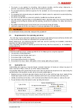
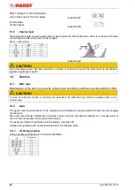
Adjusting the air gap
View "X" on the brake.
1 Loosen the locking screws (6) by half a turn.
2 Turn the cap screws (8) into the magnetic body
(9) anti-clockwise.
3 By turning the locking screws (6) clockwise,
move the magnetic body (9) towards the
anchor plate (10) using a feeler gauge until
nominal air gap “a” is reached (see table).
4 Unscrew the cap screws (8) from the magnetic
body clockwise.
5 Tighten the locking screws (6).
6 Check the air gap again and re-adjust if
necessary.
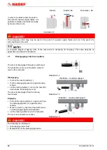
Illustration 18
12.4
Overload protection
If the hoist does not lift the permitted load, the overload protection must be adjusted. Adjustment may only be
done by a service company, authorised by the manufacturer!
DANGER!
The factory setting of the overload protection is secured by a seal. Any guarantee becomes invalid if this setting is
changed. Should maintenance be necessary, please contact a service company that is authorised by the
manufacturer.
DANGER!
The overload protection serves exclusively to protect against damage to the device due to overloading
when moving loads. Its function must not be integrated into the operational work process!
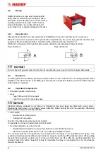
Depending on the type of hoist, the following variants are possible:
12.4.1
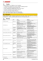
Electronic hoisting power limiter (as option, except serial AT)
Power consumption of the hoist motor is measured during lifting movement of a load
by an adjustable power measuring device (overload guard). The setting is made via a
separate relay for main and creep lifting speed. Power consumption of the motor is
load-dependent and increases with the load. If the set value is exceeded, the relay
responds and switches the motor off via switching elements. After the overload
protection has been activated the LOWER button must be pressed first so that the
LIFT function can be activated again. Before lifting again the load must be reduced to
the nominal load!
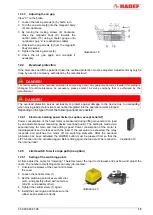
Illustration 19
12.5
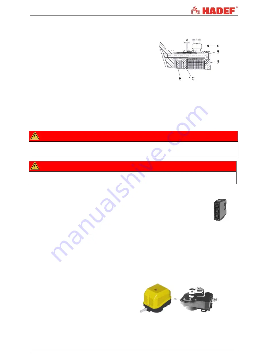
Limit switch for wire rope path (as option)
12.5.1
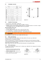
Setting of the switching points
At first, adjust the cams for "lowering". Therefore lower the load to its lowest end position and adjust the
cams. The number of switching cams can vary job-oriented.
1 Unscrew the screws of the cover and remove
the cover.
2 Loosen the central screw (1)
3 Set the switching point of every cam disc
(A,B
…and possibly other) with set screw
(2A,2B
…and possibly other).
4 Tighten the central screw (1) again.
5 Install the cover again and make sure the
rubber seal is placed correctly.
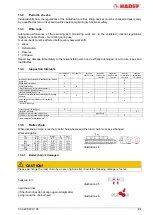
Illustration 20

