


30
Installation
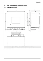
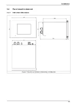
3.6
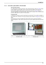
Connections to electronic boards
Note:
Any loose connection wires should be bundled tightly together with the use of nylon cable ties.
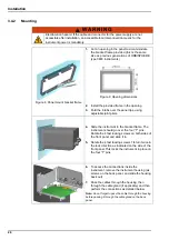
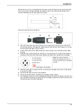
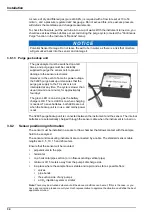
3.6.1
Sensor cable
An ORBISPHERE cable (10 wire shielded, Part N° 32505.mm) is needed to connect the
sensor(s) to the instrument. The instruments have a Lemo 10 socket on the back panel where
the sensor cable has to be connected.
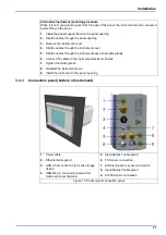
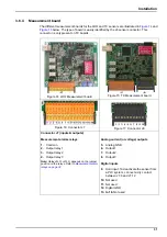
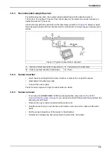
3.6.2
Electronic boards connectors
Connectors P8 on the main board, and connectors J7 and J8 on the measurement board(s) are
made of two parts. Push down carefully the black levers on either side of the connector and pull
it out securely. Perform all connections with these connectors unplugged. Once finished, attach
the connectors to the boards by pushing them firmly in place (levers up).
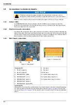
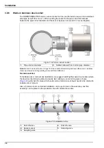
3.6.3
Main board connections
N O T I C E
Potential Instrument Damage. Delicate internal electronic components can be
damaged by static electricity, resulting in degraded performance or eventual failure.
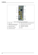
Figure 12 Main board
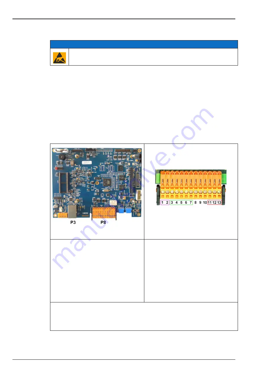
Figure 13 Connector P8
Connector P8:
1.
RS-485 (signal A)
2.
RS-485 (signal B)
3.
PROFIBUS-DP (GND)
4.
PROFIBUS-DP (+ 5 V)
5.
PROFIBUS-DP (signal -)
6.
PROFIBUS-DP ()
7.
PROFIBUS-DP (signal RTS)
8.
Not used
9.
Not used
10.
Not used
11.
System alarm relay (N.O.)
12.
System alarm relay (N.C.)
13.
System alarm relay (Common)
Connector P3
Ethernet RJ 45. Connect the wall and panel mount instruments to the local network by passing
an ethernet cable through the ethernet cable gland (refer to
for the wall
mount and
for the panel mount). Connect to the P3 connector illustrated
above.
Summary of Contents for Orbisphere 51 Series
Page 5: ...4 Table of Contents...
Page 19: ...18 Specifications...
Page 48: ...47 Section 6 View Menu Figure 33 View menu...
Page 52: ...51 Section 7 Measurement Menu Figure 36 Measurement menu...
Page 66: ...65 Section 9 Inputs Outputs Menu Figure 40 Inputs Outputs menu...
Page 68: ...67 Inputs Outputs Menu 9 4 Analog outputs Figure 41 Analog outputs menu...
Page 75: ...74 Inputs Outputs Menu...
Page 91: ...90 Communication Menu...
Page 94: ...93 Section 12 Products Menu Figure 44 Products menu...
Page 97: ...96 Global Configuration Menu...
Page 98: ...97 Section 14 Services menu Figure 46 Services menu Part 1...
Page 99: ...98 Services menu Figure 47 Services menu Part 2...
Page 103: ...102 Services menu...


