


Page 101
8.1.6 Oxygen Controller Status
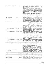
O 2 - C T R L S T A T U S 0 9 : 1 7 : 2 8 1 2 - 0 9 - 0 2
1 < I D E N T I F I C A T I O N # c 3 0 0 0 0 1 9
2 V E R S I O N 0 1 . 0 0
3 M O D E M F C / O 2
4 T E M P E R A T U R E S E N S O R 2 5 . 0 C , 1 . 2 4 V
5 A I R P R E S S S E N S O R 1 5 0 0 m b a r , 4 . 4 5 V
6 O 2 P R E S S S E N S O R 4 0 0 m b a r , 2 . 2 4 V
7 V A L V E 1 , 2 , 3 1 , 0 , 0
8 R O T A R Y V A L V E F O R W A R D
9 R O T A R Y V A L V E S E N S O R 0
1 0 M F C S E T P O I N T 2 0 . 0 l / h
1 1 M F C F L O W 1 9 . 9 l / h , 1 . 7 8 V
The O2-CTRL STATUS (Oxygen Controller Status) menu displays the system the air supply, oxygen supply,
gas flow, pressure and temperature related parameters. In BioTector, when the user enters the Oxygen
Controller Status menu or any menu, where the oxygen gas flow will be required, the oxygen generator starts
to operate automatically.
1. Identification.
Identification is the specific identification number for the Oxygen Controller Board.
2. Version.
This menu item specifies the software version of the Oxygen Controller Board.
3. Mode.
This menu item allows the Oxygen Controller Board to operate the Mass Flow Controller (MFC)
only, the Oxygen Concentrator only, or both.
4. Temperature Sensor.
This is the BioTector temperature sensor, located on the Oxygen Controller Board,
which displays the system temperature. The voltage (V) readings as obtained from the temperature
sensor are displayed in real time.
5. Air Pressure Sensor.
This menu item displays the air inlet pressure for the oxygen concentrator. The
pressure (mbar) and the voltage (V) readings as obtained from the Air Pressure Sensor are displayed in
real time.
6. O2 Pressure Sensor.
This menu item displays the oxygen inlet pressure for the Mass Flow Controller.
The pressure (mbar) and the voltage (V) readings as obtained from the Oxygen Pressure Sensor are
displayed in real time.
7. Valve 1, 2, 3.
This item displays the Oxygen Controller valve outputs for valves 1, 2 and 3. Valve 1 is the
Air Isolation Valve. See figure 6 in Section
and 3 are reserved. When Valve 1 is activated,
the displayed value is “1”. When Valve 1 is deactivated,
the displayed value is “0”.
8. Rotary Valve.
This menu item displays the operation (Forward, Reverse and Stop) of the Rotary Valve.
9. Rotary Valve Sensor.
This menu item shows the sensor position of the Rotary Valve. If the Rotary Valve
is on the sensor, the displayed value is “1”. If the valve is not on the sensor, the displayed value is “0”.
10. MFC Setpoint.
This menu item allows the user to test the Mass Flow Controller. Use this function to set
the MFC setpoint. Press the ENTER key, set the required setpoint (e.g. 60 l/h), and press the ENTER key
again. The actual flow is shown at the top of the screen. An “*” is shown when the MFC has been
activated. If the flow is 0.0 l/h, then the MFC is switched off.
11. MFC Flow.
When MFC Setpoint is programmed above, this menu item displays the actual flow and the
corresponding voltage on the MFC. When BioTector is not running, that is, when it is powered up and
stopped, or when it is in standby state, as the MFC Setpoint is 1 l/h, the MFC Flow displays the 1 l/h flow.
Summary of Contents for BioTector B3500C
Page 17: ...Page 17 Software Menu Diagram...
Page 44: ...Page 44 Figure 4 BioTector analysis layout typical TIC TOC system...
Page 46: ...Page 46 Figure 6 BioTector oxygen concentrator layout...
Page 63: ...Page 63...
Page 78: ...Page 78 Section 8 Maintenance Menu Maintenance Menu Diagram...
Page 155: ...Page 155 Section 11 System Replacement and Spare Parts...
Page 163: ...Page 163 ZK Zero check ZM Manually input zero adjust ZS Zero and Span...


