background image

80

Plumbing and Connection Options

A.5 Option 1 plumbing and connections

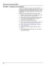
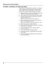
Option 1 is used with an sc analyzer and the Filter Probe sc. The 
waste from the analyzer is discharged back into the basin using the 
Filtration Kit. Use the drain tube inside the Filter Probe sc or the 
optional heated drain tube to discharge the waste stream from the 
sc analyzer. 

Refer to 

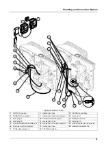
Figure 29

 and the following instructions for Option 1:

1.

Install the Filter Probe sc into the sample stream. Refer to the 
Filter Probe sc User Manual for more information. 

2.

Feed the Filter Probe sc hose (sample lines, electrical cables 
and drain tube) through the analyzer opening (item 5, 

Figure 29

). Use Seal Plug #2 to secure. 

3.

Seal the unused openings with Seal Plug #3.

4.

Connect the Filter Probe sc data cable and power connections. 
Refer to 

section 3.5.4, page 26

 and 

Figure 16, page 28

5.

Connect the air tube to the compressor (item 3). Refer to 

section 3.5.5, page 27

.

6.

Connect the drain tube to the Filter Probe sc (

Figure 29, 

page 81

). 

7.

Connect the sample line to the sample inlet on the overflow 
vessel using the fittings.

Summary of Contents for AMTAX sc

Page 1: ...DOC023 52 00025 AMTAX sc AMTAX indoor sc USER MANUAL 04 2013 Edition 8A AMTAX sc AMTAX indoor sc HACH LANGE GmbH 2006 2010 2012 2013 All rights reserved Printed in Germany sd sk...

Page 2: ......

Page 3: ...erations 25 3 5 2 Enclosure breakouts 25 3 5 3 Insert tubing and or cables 26 3 5 4 Connect the Filter Probe to the analyzer 26 3 5 5 Connect the optional heated drain 27 3 6 Installation of reagents...

Page 4: ...ESD Considerations 77 A 2 Connect a 2 parameter option 78 A 2 1 Remove the T fitting 79 A 3 Drain line considerations 79 A 4 Tubing considerations 79 A 5 Option 1 plumbing and connections 80 A 6 Opti...

Page 5: ...mg L NH4 N 0 02 to 0 2 mg L NH4 N 3 measurements shortest 15 minutes 0 2 to 5 mg L NH4 N 1 measurement 5 minutes Measuring Ranges 0 05 to 20 mg L 1 to 100 mg L and 10 to 1000 mg L NH4 N 5 minutes Adj...

Page 6: ...TAX sc W H D 540 720 390 mm 21 25 28 35 15 35 in AMTAX indoor sc W H D 540 720 370 mm 21 25 28 35 14 5 in Data and power cable lengths 2 m 80 in from edge of enclosure Weight AMTAX sc Approx 31 kg wit...

Page 7: ...7 Specifications Figure 1 Instrument dimensions AMTAX sc...

Page 8: ...8 Specifications Figure 2 Instrument dimensions AMTAX indoor sc 1 57 in 850 mm 33 15 in 720 mm 28 35 in 540 mm 21 26 in 370 mm 14 57 in...

Page 9: ...t could occur if not observed A symbol if noted on the instrument will be included with a danger or caution statement in the manual This symbol if noted on the instrument references the instruction ma...

Page 10: ...robe sc is single channel only The sc analyzer can be converted from a single channel operation to dual channel operation Contact the manufacturer for more information This symbol when noted on the pr...

Page 11: ...nclosure 1 LED for operating state Refer to Table 9 page 57 for more information 2 Door lock 3 Rating plate with model number serial number voltage and frequency information and power consumption info...

Page 12: ...12 General Information...

Page 13: ...e equipment suitable to the concentration and quantity of the dangerous material at the respective work place 3 1 Basic installation overview 1 Unpack the instrument section 3 2 2 Mount the instrument...

Page 14: ...ure 2 page 8 for instrument dimensions Make sure that the fastening has sufficient load bearing capacity approximately 160 kg The wall plugs must be selected and approved to suit the properties of the...

Page 15: ...15 Installation 4 Attach the enclosure to the fastening bracket 5 Attach the angle bracket on the enclosure to the wall Figure 5 Bracket dimensions for wall mounting...

Page 16: ...16 Installation Figure 6 Wall mounting the analyzer 1 Socket head cap screw M5 X 8 2X 4 Screw customer supplied 2 Washer M5 4X 5 Socket head cap screw M5 X 40 2X 3 Angle bracket 6 Fastening bracket...

Page 17: ...The enclosure may tip forwards if it has not been fixed in place Only open the enclosure if the enclosure is properly mounted 1 Unlock the instrument item 4 Figure 7 item 3 Figure 8 2 Open the side la...

Page 18: ...18 Installation Figure 8 Open the enclosure AMTAX indoor sc 1 Latches 3 Lock with key 2 Door hook...

Page 19: ...for the measuring unit is NOT a transport lock Do NOT remove the cover on the measuring unit 1 Open the enclosure door and secure with the door hook 2 Remove the transport lock on the analyzer panel F...

Page 20: ...ock removal1 1 Compressor transport lock 4 Protective cover for compressor 2 Cable tie 5 Fan locking screw 3 Compressor 6 Fan 1 The compressor compressor transport lock and cable tie only apply to sc...

Page 21: ...wards if it has not been fixed in place Only open the enclosure if the enclosure is properly mounted 1 Open the enclosure door and secure with the door hook 2 Slide the collecting tray into the bottom...

Page 22: ...y open the enclosure if the enclosure is properly mounted 1 Remove power from the instrument 2 Open the enclosure door and secure with the door hook 3 Connect the humidity sensor wires to the terminal...

Page 23: ...2 1 5 A 9 page 88 2 FILTRAX 2 heated 2 2 2 6 A 10 page 90 INDOOR Filter Probe sc Unheated 1 1 1 7 A 11 page 92 FILTRAX Unheated 1 1 1 8 a A 12 page 94 2 1 2 8 b A 13 page 96 2 FILTRAX Unheated 1 2 1...

Page 24: ...less a qualified installation technician is installing wiring for the Filter Probe sc or the heated drain See Figure 14 for protective cover removal Figure 13 Sealing plug types 1 Sealing plug type 1...

Page 25: ...an be accomplished by touching an earth grounded metal surface such as the chassis of an instrument or pipe or a metal conduit To reduce static build up avoid excessive movement Transport static sensi...

Page 26: ...t the earth ground green yellow wire item 9 Figure 16 page 28 from the Filter Probe sc to the ground terminal item 5 Figure 16 page 28 5 Connect the power connector to the appropriate terminal connect...

Page 27: ...nect the heated drain 1 Open the enclosure door and secure if necessary 2 Open the analyzer panel 3 Remove the protective cover Figure 14 page 24 4 Connect the earth ground wire green yellow to the gr...

Page 28: ...be sc ground wire 3 Heated drain optional power connector 10 Filter Probe sc data cable connector 4 Filter Probe sc power connector 11 Filter Probe sc power cable connector 5 Ground wire terminal stri...

Page 29: ...oncentration and quantity of the dangerous material at the respective work place CAUTION Avoid unnecessary contact with sample flows of unknown concentration This can produce hazards due to trace chem...

Page 30: ...1012 28258 54 50 mg L CAL 2 Standard 2 high light blue BCF1149 25147 54 BCF1011 28943 54 10 mg L BCF1021 58958 54 50 mg L BCF1013 28259 54 500 mg L Reagent orange BCF1009 28944 52 BCF1009 28944 52 BCF...

Page 31: ...supplied enclosure To prevent inaccurate readings or instrument malfunction do not use a different enclosure than that supplied by the manufacturer 3 7 1 1 Fill the electrode with electrolyte CAUTION...

Page 32: ...nd fill the body with an entire bottle of electrolyte 11 mL Gently tap the side of the body to remove any air bubbles Note To prevent inaccurate results the electrolyte volume should be between 4 mL a...

Page 33: ...e mains where necessary Therefore make sure that socket to which the device is connected is easy to reach by each user at all times Important Note Unless the sc1000 that connects to the AMTAX sc analy...

Page 34: ...tlets corresponds to the mains voltage that is customary in the country in question and to which the controller is connected A device designed for 115 V must not be connected to a controller with a hi...

Page 35: ...e information The factory settings default setting are appropriate for most typical applications 3 From SENSOR SETUP select AMTAX sc MAINTENANCE TEST MAIN 4 Select the PREPUMP ALL function and confirm...

Page 36: ...36 System Start Up...

Page 37: ...ation then measuring mode CAL CLEAN Triggers an automatic calibration with subsequent automatic cleaning then measuring mode SETTINGS SET OUTMODE Value that is output during a calibration and the foll...

Page 38: ...mber of measurements that are averaged Affects only the bus triggered measurements CLEANING SET INTERVAL Number of hours between the cleanings START Start time for the cleaning In case of more than on...

Page 39: ...ION Indication of instrument option filtration probe 1 channel 2 channel SOFTWARE PROBE Filtration probe software SOFTW AMTAX Instrument software LOADER Detailed information on the software in the ins...

Page 40: ...om 90 days Negative values indicate that electrolyte change is overdue Reset by CHANGE MEMBRANE or CHANGE ELECTRODE process TEST MAINT Maintenance processes SIGNALS PROCESS Indication of what the inst...

Page 41: ...n probe is registered sample is pumped from the filtration probe for 1 minute MODULE CLEAN Menu based process for cleaning the filter modules automatically resetting the maintenance counter With filtr...

Page 42: ...minutes After a successful calibration the instrument automatically returns to the measurements Note When the instrument detects and displays a warning the measurement process will continue Refer to...

Page 43: ...rocess This process takes approximately 15 minutes when the instrument temperature is 15 C 59 F Note Lower instrument temperatures prolong the warming up phase Note From the service mode press START t...

Page 44: ...44 Operation...

Page 45: ...ry information printed on the original solution containers and safety data sheet prior to their use Dispose of all consumed solutions in accordance with national regulations and laws Select the type o...

Page 46: ...TER 3 Select START and press ENTER The process is started and the cooling fan stops Important Note Open the instrument door to prevent overheating CAUTION Avoid injury Keep hands clear Although the fa...

Page 47: ...5 for information on the life of the chemicals Table 5 Chemicals for the AMTAX sc Chemical section 8 1 page 65 Measuring range 1 0 02 5 mg L Measuring range 2 0 05 20 mg L Measuring range 3 1 100 mg...

Page 48: ...cap and electrolyte if necessary X1 X Check system for air impermeability X Function check of both fans X Function check heating for analyser enclosure X General function check X Read out and analyse...

Page 49: ...operating the instrument the amount of electrolyte should be between 4 mL and 11 mL With less amount of electrolyte the accuracy will be reduced for low measured values in the related measuring range...

Page 50: ...he electrode to the clamp on the analyzer panel Do not touch the membrane 4 Drain the electrolyte from the electrode body Important Note Never add new electrolyte on top of old electrolyte Always empt...

Page 51: ...he next calibration follows and after four hours it calibrates for the last time Then the instrument changes to the adjusted calibration cycle Note There is no warning concerning the electrode slope d...

Page 52: ...alue 3 value range 2 to 10 6 Select START after adjusting both parameters and the analyzer is going into the service state The remaining time is displayed in seconds The OUTMODE is set to HOLD 7 Selec...

Page 53: ...vent log records the validation values and average value from the analyzer 10 Press ENTER to proceed Note Press START to confirm the inquiry to return to the measurement process or to the service mode...

Page 54: ...n 3 Clean the canister lid with distilled water 4 Take the tubing out of the water and start the FLUSHING function to pump the tubing and the analysis instrument empty 5 Wipe the canister lids dry and...

Page 55: ...er can be converted from single channel to dual channel operation and or continuous sampling Contact the manufacturer for more information Refer to Table 8 for configuration options Table 8 Conversion...

Page 56: ...56 Maintenance...

Page 57: ...k all relevant settings 5 If the problem still occurs contact Technical Support 7 2 Troubleshooting the analyzer If the complete analysis instrument is not working check whether the humidity sensor ha...

Page 58: ...n and contact service Take the filtration probe sc out of the tank and store the filter modules so that they remain moist See operating instructions for the filtration probe sc Reset error manually PR...

Page 59: ...cleaning solution level and delivery and sample delivery check Standard 1 level and if correct for measurement range change membrane and elektrolyte Error may occure when sample has very unusual prop...

Page 60: ...dules is disabled so as to generate less heat internal temp target temp of cuvette Change clean air filter check air ducts for blockage check enclosure fan is ambient temperature allowed If necessary...

Page 61: ...cessary then reset standard level The level is indicated mathematically and can only function reliably if the counter is only reset when the solution is changed On the menu MAINTENANCE MAINT COUNTER S...

Page 62: ...o 55 mV or 67 to 70 mV Slope error 0 to 50 mV or 70 to 150 mV mV zero 205 to 5 mV 20 to 120 mV 20 to 120 mV 20 to 120 mV mV standard 1 200 to 140 mV 30 to 30 mV 25 to 85 mV 70 to 130 mV mV standard 2...

Page 63: ...L NH4 N is adjusted and the wrong standard solutions 10 and 50 mg L NH4 N are used Insert the right standard solutions and complete the procedure for changing the measuring range in the service menu...

Page 64: ...64 Troubleshooting...

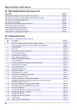
Page 65: ...NH4 N BCF1021 28958 54 Set of reagents AMTAX sc with standard solution Measurement range 4 10 1000 mg L NH4 N LCW866 Reagent AMTAX sc 2 5 L for all measurement ranges BCF1009 28944 52 CAL1 Standard 50...

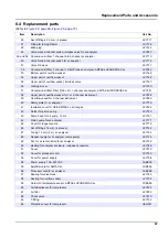
Page 66: ...4 Set of filter pads 2 pieces LZY154 5 Clamping lock for sc analyzer LZY147 6 Fence includes screws M3 x 6 LZY157 7 Compressor switchable 115V 230V LZY149 8 Fan for incoming air LZY152 9 Air tubing fo...

Page 67: ...sc analyzer LZY179 41 Insulation cover for GSE AMTAX sc all ranges LZY224 42 Holder for piston pump LZY180 43 Pump head for air pump 10 mL LZY181 44 Piston pump for sc analyzer LZY177 45 Cover for re...

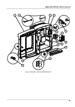
Page 68: ...68 Replacement Parts and Accessorie Exploded view drawings Figure 22 Analyzer enclosure AMTAX sc...

Page 69: ...69 Replacement Parts and Accessorie Figure 23 Analyzer enclosure AMTAX indoor sc...

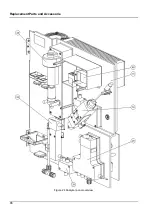
Page 70: ...70 Replacement Parts and Accessorie Figure 24 Analyzer panel overview...

Page 71: ...71 Replacement Parts and Accessorie Figure 25 Analyzer panel front view details...

Page 72: ...72 Replacement Parts and Accessorie Figure 26 Analyzer panel back view details...

Page 73: ...ax 32 0 15 41 61 20 info hach lange be www hach lange be DR LANGE NEDERLAND B V Laan van Westroijen 2a NL 4003 AZ Tiel Tel 31 0 344 63 11 30 Fax 31 0 344 63 11 50 info hach lange nl www hach lange nl...

Page 74: ...HR 42 000 Vara din Tel 385 0 42 305 086 Fax 385 0 42 305 087 info hach lange hr www hach lange hr HACH LANGE MAROC SARLAU Villa 14 Rue 2 Casa Plaisance Quartier Racine Extension MA Casablanca 20000 T...

Page 75: ...t 7 days after the identification of the fault If the customer fails to notify the supplier the product is considered approved despite the defect Further liability for any direct or indirect damages i...

Page 76: ...76 Warranty and liability...

Page 77: ...rmed with power removed Delicate internal electronic components can be damaged by static electricity resulting in degraded instrument performance or eventual failure The manufacturer recommends taking...

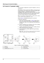
Page 78: ...llowing instructions to connect a 2 parameter configuration 1 Remove the small blind plug item 1 Figure 27 from the top hole on the overflow vessel Remove the large fitting item 2 from the bottom hole...

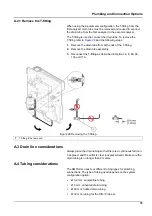
Page 79: ...drain tube assembly 3 Reconnect the T fitting as described in Options 4 6 8b 9b 10b and 11b A 3 Drain line considerations Always place the drain tubing so that there is a continuous fall min 3 degree...

Page 80: ...Probe sc into the sample stream Refer to the Filter Probe sc User Manual for more information 2 Feed the Filter Probe sc hose sample lines electrical cables and drain tube through the analyzer opening...

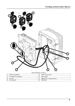
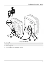
Page 81: ...umbing and Connection Options Figure 29 Option 1 setup 1 AMTAX sc analyzer 5 Filter Probe sc hose 2 PHOSPHAX sc analyzer 6 Seal plug 2 3 Air tube 7 Sample line to overflow vessel 4 Seal plug 3 8 Drain...

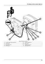
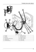
Page 82: ...hrough the analyzer opening item 9 Figure 30 Use Seal Plug 2 to secure Note The drain tube from the Filter Probe sc is not used 3 Feed the heated drain hose through the analyzer opening item 7 Use Sea...

Page 83: ...1 AMTAX sc analyzer 7 Heated drain tube 2 PHOSPHAX sc analyzer 8 Seal plug 1 3 Unused heated drain sample lines 9 Filter Probe sc hose 4 Unused Filter Probe sc drain tube 10 Seal plug 2 5 Air tube 11...

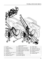
Page 84: ...X into the sample stream Refer to the FILTRAX User Manual for more information 2 Feed the heated hose from the FILTRAX through the analyzer opening Figure 31 item 5 Use Seal Plug 1 to secure 3 Feed th...

Page 85: ...g and Connection Options Figure 31 Option 3 setup 1 Unused heated drain sample lines 5 FILTRAX heated hose 2 Seal plug 3 6 Seal plug 1 3 Heated drain hose 7 FILTRAX sample line 4 Seal plug 1 8 Heated...

Page 86: ...move the T fitting from the drain tube item 7 Retain for reuse with Analyzer 2 f Connect the heated drain tube to the valve block connector g Connect the sample line from the FILTRAX to the bottom inl...

Page 87: ...zer 1 16 Seal plug 1 3 Seal plug 1 10 Sample line from analyzer 1 17 Heated drain hose 4 Seal plug 3 11 Heated drain hose 18 Seal plug 3 5 Unused heated drain sample lines 12 Heated drain hose from an...

Page 88: ...ion 2 Feed the heated hose from FILTRAX 1 through the analyzer opening Figure 33 item 7 Use Seal Plug 1 to secure 3 Feed the heated hose from FILTRAX 2 through the analyzer opening item 6 Use Seal Plu...

Page 89: ...p 1 FILTRAX 1 7 FILTRAX heated hose 1 2 FILTRAX 2 8 Heated drain hose tube 3 Seal plug 1 9 FILTRAX 2 sample line 4 Unused heated drain sample lines 10 FILTRAX 1 sample line 5 Heated drain hose 11 Over...

Page 90: ...tor f Connect the sample line from FILTRAX 1 to the bottom inlet on Overflow Vessel 1 using the fittings item 20 g Connect the sample line from FILTRAX 2 to the bottom inlet on Overflow Vessel 2 using...

Page 91: ...e line 4 FILTRAX 2 14 Heated drain sample 2 from analyzer 1 24 Heated drain 2 sample line 5 Seal plug 1 15 Heated drain sample 1 from analyzer 1 25 FILTRAX 1 heated hose 6 Seal plug 3 16 Overflow vess...

Page 92: ...tall the Filter Probe sc into the sample stream Refer to the Filter Probe sc User Manual for more information 2 Feed the Filter Probe sc hose sample lines electrical cables drain tube through the anal...

Page 93: ...ion Options Figure 35 Option 7 setup 1 AMTAX sc analyzer 6 Filter Probe sc hose 2 PHOSPHAX sc analyzer 7 Seal plug 2 3 Unused Filter Probe sc drain tube 8 Sample line to overflow vessel 4 Air tube 9 D...

Page 94: ...he FILTRAX User Manual for more information 2 Feed the heated hose from the FILTRAX through the analyzer opening Figure 36 item 3 Use Seal Plug 1 to secure 3 Feed the drain tube through the analyzer o...

Page 95: ...95 Plumbing and Connection Options Figure 36 Option 8a Setup 1 Seal plug 3 2 Seal plug 1 3 FILTRAX heated hose 4 FILTRAX sample line 5 Drain tube Feed to a lower drain maximum 2 m 6 5 ft...

Page 96: ...the analyzer to the 2 parameter configuration Refer to Connect a 2 parameter option page 78 d Connect the reworked overflow of the overflow vessel to deliver the sample to Analyzer 2 e Feed the overf...

Page 97: ...TRAX sample line 2 PHOSPHAX sc analyzer 8 FILTRAX heated hose 3 Seal plug 3 9 Seal plug 1 4 Sample line from analyzer 1 maximum 2 m 6 5 ft 10 Seal plug 3 5 Drain tube Feed to a lower drain maximum 2 m...

Page 98: ...sample stream Refer to the FILTRAX User Manual for more information 2 Feed the heated hose from FILTRAX 1 through the analyzer Figure 38 item 6 Use Seal Plug 1 to secure 3 Feed the heated hose from F...

Page 99: ...up 1 FILTRAX 1 5 FILTRAX 2 heated hose 9 FILTRAX 1 sample line 2 FILTRAX 2 6 FILTRAX 1 heated hose 10 Overflow vessel 1 3 Seal plug 1 7 Drain tube Feed to a physically lower drain maximum 2 m 6 5 ft 1...

Page 100: ...Remove the drain tube with the T fitting from the valve block connector e Connect the drain tube to the valve block connector f Connect the sample line from FILTRAX 1 to the bottom inlet on Overflow...

Page 101: ...be 3 PHOSPHAX sc analyzer 10 Overflow vessel 2 17 Overflow vessel 2 tube 4 FILTRAX 2 11 Drain tube Feed to a lower drain maximum 2 m 6 5 ft 18 FILTRAX 1 heated hose 5 Seal plug 3 12 FILTRAX 2 sample l...

Page 102: ...ions for Option 10a 1 Install the sample preparation unit 2 Feed the sample line from the sample preparation unit through the analyzer Figure 40 item 2 Use Seal Plug 3 to secure 3 Feed the drain tube...

Page 103: ...103 Plumbing and Connection Options Figure 40 Option 10a setup 1 Seal plug 3 2 Sample line 3 Drain tube Feed to a lower drain maximum 2 m 6 5 ft...

Page 104: ...gure 41 item 7 Use Seal Plug 3 to secure b Feed the drain tube through the analyzer item 6 Use Seal Plug 3 to secure c Remove the drain tube from the valve block connector d Connect the sample line fr...

Page 105: ...0b setup 1 AMTAX sc analyzer 4 Sample line from analyzer 1 7 Sample line 2 PHOSPHAX sc analyzer 5 Drain tube Feed to a lower drain maximum 2 m 6 5 ft 8 Seal plug 3 3 Seal plug 3 6 Drain tube Feed to a...

Page 106: ...from each sample preparation unit through the analyzer Use Seal Plug 3 to secure 3 Feed the drain tube through the analyzer using Seal Plug 3 Figure 42 item 2 Note Tubes can be pushed through prepared...

Page 107: ...and Connection Options Figure 42 Option 11a setup 1 Seal plug 3 3 Sample line preparation 2 5 Overflow vessel 1 2 Drain tube Feed to a lower drain maximum 2 m 6 5 ft 4 Sample line preparation 1 6 Over...

Page 108: ...tting from the valve block connector Connect the drain tube to the valve block connector Discard the T fitting e Connect Sample Line 1 from Sample Preparation Unit 1 to the bottom inlet on Overflow Ve...

Page 109: ...nalyzer 2 overflow vessel 1 3 Seal plug 3 9 Drain tube Feed to a lower drain maximum 2 m 6 5 ft 15 Sample Line to Analyzer 2 overflow vessel 2 4 Drain tube Feed to a lower drain maximum 2 m 6 5 ft 10...

Page 110: ...110 Plumbing and Connection Options...

Page 111: ...internal processes like calibration and cleaning are interrupted by a forced measurement The interrupted process will be started again after the forced measurement A discharged value will be discarde...

Page 112: ...er contact Control by external signal If the controller board is equipped with an external input terminal optional board version measurements can be issued by applying an external DC voltage of 15V to...

Page 113: ...in correction for channel 1 mV SLOPE 40046 Float 2 R 3000 3000 SLOPE of electrode BUSACTION ACTIVE 40048 Unsigned Integer 1 R W 0 1 Enter 1 to start a BUS action see Fieldbus control BUS ANALY START 4...

Page 114: ...egative values show overdue cleaning exchange of air filter pads COOLING 40077 Unsigned Integer 1 R 0 100 Percentage of cooling fan power ANALYZER HEATING 40078 Unsigned Integer 1 R 0 100 Heating of t...

Page 115: ...in percent PROCESS STATE 40107 Unsigned Integer 1 R 0 1 2 3 4 5 6 7 8 9 10 11 12 13 14 15 16 17 18 19 20 Process status is coded as enum list enum value 0 service mode enum value 1 citrocal in proc ca...

Page 116: ...teger 1 R 0 100 Level of reagent in percent CLEAN SOLU LEVEL 40144 Unsigned Integer 1 R 0 100 Cleaninig solution level in percent STANDARDS LEVEL 40146 Unsigned Integer 1 R 0 100 Level of standards in...

Page 117: ...TIME 40242 Time2 2 R 9 TH LAST TIME ACTUAL VALUE 40244 Float 2 R 0 15000 Actual measurement value not channel dependent LAST VALUE 40246 Float 2 R 0 15000 LIST OF VALUES 2 ND LAST VALUE 40248 Float 2...

Page 118: ...C 32 F bit 1 ANALYZ TO COLD COOLING FAILED HUMIDITY ANALY HUMIDITY PROBE PROBE MISSING NO HEAT UP CUVSENSOR DEFECT TEMPSENS DEFECT CUVHEAT DEFECT CUV TOO HOT ELECTRODE SLOPE FALSE ELEC DATA MODULES CO...

Reviews: