background image

14

Replacement


parts


list

Pos.

Description

Piece

No. PR

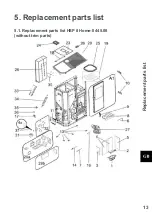
Replacement


parts


list


HSP


8


Home

-II 445.08 

(without


trim


parts)

A1

Complete combustion chamber door/pearly-

black

1 piece

0544208005300

1

Burner cast

1 piece

0544208006762

2

Protection grate

1 piece

0544208006713

3

Combustion chamber cladding left

1 piece

0544208005507

4

Combustion chamber cladding back

2 piece

0544208005505

5

Combustion chamber cladding right

1 piece

0544208005506

6

Flame temperature sensor

1 piece

0544008007511

7

Bottom temperature sensor

1 piece

0544008007539

8

Draught baffle plate

1 piece

0544208005752

9

Door contact switch

1 piece

0089500040005

10

Door hinge pearly-black

1 piece

0544008005450

11

Complete control unit

1 piece

05

5

1908005569

12

Backup battery CR 2032

1 piece

13

Stand

6 piece

0082000105000

14

Ignition

1 piece

0541908005202

15

Room temperature sensor

1 piece

0089500390005

16

Flue gas thermosensor

1 piece

0561008005540

17

STB

1 piece

0089500080005

18

Cover hinge

2 piece

05445080

46113

19

Protective grille

1 piece

05445080

45971

20

Cover pearly-black

1 piece

05445080

4

6180

23

Tank cover pearly-black

1 piece

05445080

46150

24

Operator console

1 piece

05

51908005569

25

Seal, tank cover

1060 mm

05445080

4

5929

26

Handle

1 piece

0544008007581

27

Induced draught fan

1 piece

0561008005807

28

Heat exchanger

1 piece

0544

0

08006000

29a

Seal - set

10 piece

0544508015011

29b

Seal - set cleaning

2 piece

0544408005012

30

Tank cover + screw DIN 7981 ST 4,8x13 - set 1+4 piece

0544008005019

31

Screw conveyor motor

1 piece

0089500000006

32

Motor plate - set

1 piece

0561008007080

33

Conveyor

1 piece

0544008005938

34

Screw conveyor

1 piece

0544008007090

35

Lower screw conveyor bearing

1 piece

0544008007047

36

Collet

1 piece

0089000340005

37

Screw UN5950 M5x10

4 piece

Summary of Contents for HSP 8 Home-II 445.08

Page 1: ...Fiche technique Po le pellets FR Scheda tecnica Stufe pellet IT Equipment sheet Pellet stove GB Tehni ki list Kotel na pelete HR Tehni ni list Kotel na pelete SLO 0544508049033 HSP 8 Home 445 08 Tech...

Page 2: ...heating device or of an injury The note entitled Notice advises you on possible damage to your heating device The note entitled Important calls your attention to the information important for the ope...

Page 3: ...5 4 2 Cleaning the pellet container annual maintenance 7 4 1 Cleaning the flue gas passes annual maintenance 5 4 3 The left side of the device to the unit during dismantling of the enclosure access 8...

Page 4: ......

Page 5: ...n of dust in flue gas 24 mg Nm Contents of storage container pellet tank ca 32 kg Duration of burn with one charge min max ca 20 h 60 h Permitted fuel Low dust wood pellets Durchmesser 6 mm to Norm M...

Page 6: ...Dimensions 2 2 Dimensions...

Page 7: ...longer than 30 operating hours However this instruction to clean the combustion chamber display flashing does not trigger an error message during Heating mode If the combustion chamber is now cleaned...

Page 8: ...ing in the pellet tank might possibly result This will destroy your device and is not covered in your guarantee WARNING Cleaning the combustion pot may only be done with a cooled down stove in OFF ope...

Page 9: ...guarantee claims 4 1 Cleaning the flue gas passes annual maintenance CAUTION Check and clean the flue gas ways exhaust flue gas fan and flue gas ducts at the latest after 1000 kg of pellets have been...

Page 10: ...ls are required to disassemble CAUTION After completion of the cleaning make sure that when putting back the covers the seals are seated in the right positions It is essential to replace defective sea...

Page 11: ...in the pellet tank may be removed Then clean the tank and the intake of the screw conveyor housing with a vacuum cleaner After cleaning it is essential to put back the protective grille When doing th...

Page 12: ...Maintenance work 8 4 3 The left side of the device to the unit during dismantling of the enclosure access 4 3 a 4 3 b...

Page 13: ...Maintenance work 9 4 3 c 4 3 d...

Page 14: ...Maintenance work 10 4 3 e Cross head screwdriver 4x screw M5x16 were removed The following tools are required to disassemble...

Page 15: ...9 See arrows Remove the induced draught motor by pulling it out Now clean the flue gas passes the induced draught fan and the flue tubes with a brush and an ash vacuum cleaner Then reassemble the comp...

Page 16: ...Maintenance work 12 4 3 2 Cleaning annual Chimneys CAUTION The exhaust pipes are checked and if necessary must be cleaned after the latest max heating 1000kg of pellets...

Page 17: ...13 Replacement parts list 5 Replacement parts list 5 1 Replacement parts list HSP 8 Home II 445 08 without trim parts...

Page 18: ...0082000105000 14 Ignition 1 piece 0541908005202 15 Room temperature sensor 1 piece 0089500390005 16 Flue gas thermosensor 1 piece 0561008005540 17 STB 1 piece 0089500080005 18 Cover hinge 2 piece 054...

Page 19: ...ly gray 1 piece 0544508046194 39 Front part left pearly black 1 piece 0544508046163 41 Front part right pearly black 1 piece 0544508046185 49 Front part pearly gray 1 piece 0544508016171 49 Front part...

Page 20: ...8005223 A1 4 Glass holder 2 Set 1 piece 0544208005224 64 Combustion chamber door black 1 piece 65 Seal glass 10x2 mm 2300 mm 0040210020005 66 Door glass 795x335x5 1 piece 0544208005301 67 Seal door 8...

Page 21: ...17 6 Circuit diagram Circuit diagram IO 33 3 Circuit diagram...

Page 22: ...7 Induced draught 8 IX OC 35 36 Flue gas temperature sensor 37 38 Flame temperature sensor 39 40 Room temperature sensor 41 42 Bottom flame temperature sensor 43 44 Door contact switch 48 50 Flue gas...

Page 23: ...19...

Page 24: ......

Reviews: