background image

Maintenance

work

6

4.2. Cleaning the flue gas passes - annual maintenance

CAUTION

We therefore recommend checking and/or cleaning the flue gas passes after 1,000 kg of pellets at the latest.

To clean the flue gas passes, proceed as follows:

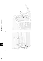
• Disconnect the flue baffle (1) from the guide by lifting it. Draw the right cladding (2) down out of the guide

and place it down in the ash space. Then the flue baffle can be removed and the upper part of the
combustion chamber can be cleaned. (See Figure 8).

• Then remove the right side wall. This is fixed with screws (1) at the back and at the front with 3 connectors.

Remove the screws from the back and pull the side wall off sideways. (See Figure 1a-2h).

Figure 8: Removing the flue baffle

Summary of Contents for HSP 8 Home 445.08

Page 1: ...Fiche technique Poêle à pellets FR Scheda tecnica Stufe pellet IT Equipment sheet Pellet stove GB Tehnički list Kotel na pelete HR Tehnični list Kotel na pelete SLO 0544508019030 HSP 8 Home 445 08 Technical documentation HSP 8 Home 445 08 V17 J31 ...

Page 2: ...e heating device or of an injury The note entitled Notice advises you on possible damage to your heating device The note entitled Important calls your attention to the information important for the operation of your heating device The note itself calls your attention to the information important for the operation of your heating device in general ...

Page 3: ...rk 5 4 1 Cleaning the pellet container annual maintenance 5 4 2 Cleaning the flue gas passes annual maintenance 6 4 3 The left side of the device to the unit during dismantling of the enclosure access 11 4 3 1 Cleaning the vent fan 15 4 3 2 Cleaning annual Chimneys 15 5 Replacement parts list 16 5 1 Replacement parts list HSP 8 Home 445 08 without trim parts 16 5 2 Replacement parts list HSP 8 Hom...

Page 4: ......

Page 5: ...f dust in flue gas 24 mg Nm Contents of storage container pellet tank ca 32 kg Duration of burn with one charge min max ca 20 h 60 h Permitted fuel Low dust wood pellets Durchmesser 6 mm to Ö Norm M 7135 DIN plus EN plus A1 Länge max 30 mm Room heating capacity to Ö Norm M 7521 max 230 m Room heating capacity to DIN 18893 Dauerheizung 250m 145m 98m Room heating capacity to DIN 18893 Zeitheizung 16...

Page 6: ...Dimensions 2 2 Dimensions ...

Page 7: ... longer than 30 operating hours However this instruction to clean the combustion chamber display flashing does not trigger an error message during Heating mode If the combustion chamber is now cleaned then the Clean combustion chamber error message will thereafter be cleared automatically A precondition for the automatic clearance of this error message is that the combustion chamber door is open f...

Page 8: ...ring in the pellet tank might possibly result This will destroy your device and is not covered in your guarantee WARNING Cleaning the combustion pot may only be done with a cooled down stove in OFF operating mode Otherwise there is a risk of burns Take out the burner bowl from the stove Remove the remains of ashes and slag After the cleaning mount the burner bowl back to its proper position on the...

Page 9: ...ING Devices that are not maintained in accordance with our specifications must not be operated Failure to observe this point will invalidate all guarantee claims 4 1 Cleaning the pellet container annual maintenance Heat the pellet stove until the storage tank is completely empty Then the protective grille 1 in the pellet tank may be removed Then clean the tank and the intake of the screw conveyor ...

Page 10: ... baffle 1 from the guide by lifting it Draw the right cladding 2 down out of the guide and place it down in the ash space Then the flue baffle can be removed and the upper part of the combustion chamber can be cleaned See Figure 8 Then remove the right side wall This is fixed with screws 1 at the back and at the front with 3 connectors Remove the screws from the back and pull the side wall off sid...

Page 11: ...Maintenance work 7 2 a 2 b ...

Page 12: ...Maintenance work 8 2 c 2 d ...

Page 13: ...Maintenance work 9 2 e 2 f ...

Page 14: ...lowing tools are required to disassemble Cross head screwdriver Allen key 4 mm 5 mm Wrench 8 mm 10 mm CAUTION After completion of the cleaning make sure that when putting back the covers the seals are seated in the right positions It is essential to replace defective seals ...

Page 15: ...Maintenance work 11 4 3 The left side of the device to the unit during dismantling of the enclosure access 4 3 a 4 3 b ...

Page 16: ...Maintenance work 12 4 3 c 4 3 d ...

Page 17: ...Maintenance work 13 4 3 e 4 3 f ...

Page 18: ...Maintenance work 14 4 3 g 4 3 h ...

Page 19: ...lean the flue gas passes the induced draught fan and the flue tubes with a brush and an ash vacuum cleaner Then reassemble the components in reverse order CAUTION Make sure that the seal is seated in the right position again It is essential to replace defective seals Make sure of the electrical connections on the fan motor and their correct positions Figure 9 Induced draught fan 1 Screw 2 Blower m...

Page 20: ...Replacement parts list 16 5 Replacement parts list 5 1 Replacement parts list HSP 8 Home 445 08 without trim parts ...

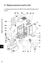
Page 21: ...2000105000 14 Ignition 1 piece 0541908005202 15 Room temperature sensor 1 piece 0089500390005 16 Flue gas thermosensor 1 piece 0561008005540 17 STB 1 piece 0089500080005 18 Cover hinge 2 piece 0544508016196 19 Protective grille 1 piece 0544508015093 20 Cover pearly black 1 piece 0544508016180 23 Tank cover pearly black 1 piece 0544508016190 24 Operator console 1 piece 0541908005569 25 Seal tank co...

Page 22: ...5 08 38 Side wall left white 1 piece 0544508016121 38 Side wall left pearly gray 1 piece 0544508016101 39 Front part left pearly black 1 piece 0544508016163 41 Front part right pearly black 1 piece 0544508016185 49 Front part pearly gray 1 piece 0544508016171 49 Front part white 1 piece 0544508016181 51 Back wall 1 piece 0544508017207 ...

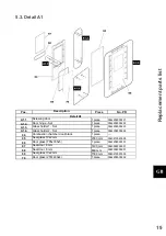
Page 23: ...der 1 Set 1 piece 0544208005223 A1 4 Glass holder 2 Set 1 piece 0544208005224 64 Combustion chamber door black 1 piece 65 Seal glass 10x2 mm 2300 mm 0040210020005 66 Door glass 795x335x5 1 piece 0544208005301 67 Seal door 8 mm 1400 mm 0040008005001 68 Seal door 8 mm 800 mm 0040008005001 69 Seal glass 10x2 mm 1500 mm 0040210020005 70 Door glass 257x400x4 1 piece 0544208005302 ...

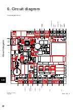
Page 24: ...1 IO33B Batterie ext H5 H6 µ SD 337960 erstellt bu 2017 10 24 freigegeben weiss Türkontaktschalter grün Drehzahl Saugzug weiss Flammen Temp unten Raumtemperatur schwarz Abgastemp ungepolt grün rot rot weiss blau rot weiss braun W LAN Modul 8041311833_B weiss Schnecke Reserve Eingang 230VAC weiss ge gn Netz STB Zündelement braun Saugzug blau rot braun blau schwarz blau braun weiss Flammen Temp oben...

Page 25: ...r 7 Induced draught 8 IX OC 35 36 Flue gas temperature sensor 37 38 Flame temperature sensor 39 40 Room temperature sensor 41 42 Bottom flame temperature sensor 43 44 Door contact switch 48 50 Flue gas fan rotation speed F1 Fuse T 3 15A ignition induced draught fan screw conveyor motor F2 Fuse T 3 15A reserve F3 Fuse T 0 315A operator console ...

Reviews: