STEP 8
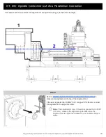
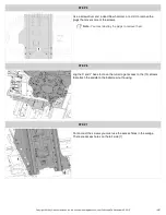
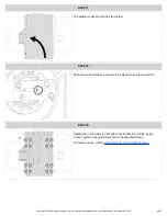
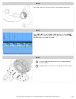
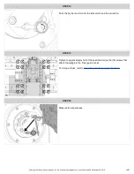
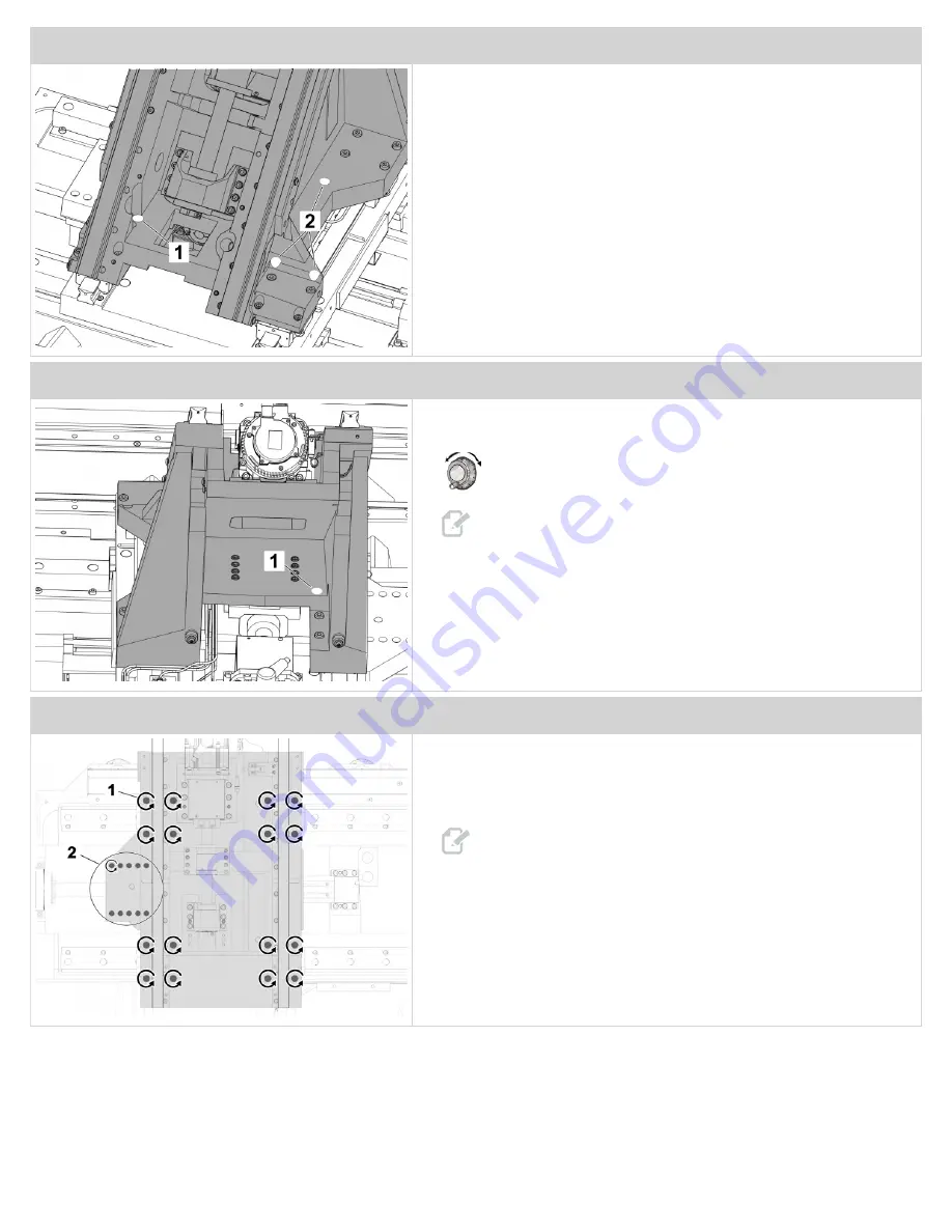
There is an access hole on the inside [1], and there are access holes on
the right side [2].
STEP 9
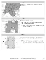
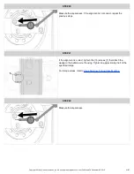
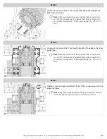
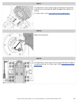
There is also an access hole in the rear.
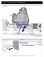
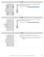
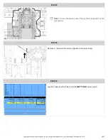
Jog the Y Axis to move the access holes to the correct
positions to loosen the screws.
Note:
You must jog the X Axis to near the middle of travel to jog
the Y Axis the full distance.
STEP 10
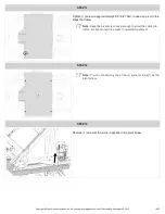
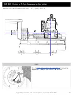
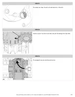
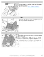
Loosen a small amount the (16) screws [1] that attach the saddle to the
linear guide trucks, and the (10) screws [2] that attach the saddle to the
ballscrew nut housing.
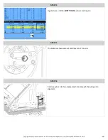
Note:
After you loosen the screws, tighten them enough to let
you control the adjustment, but keep them loose enough to let
you correct the alignment. This is approximately 5-10 ft-lb (7-14
Nm).
Copyright 2018 by Haas Automation, Inc. No unauthorized reproduction | Last Published On November 05, 2015
17/67


