2
Small VF
(not shown):
Remove the enclosure panel located below the
control cabinet.
Route the temperature sensor cable and coolant
chiller power cable to the hole in the bottom of
the control cabinet.
Note:
Follow the existing coolant cables
routing.
Use the provided magnet and cable tie to secure
the cables to the enclosure.
Inside the control cabinet route the temperature
sensor cable through the cable carriers to I/O
PCB plug P44.
Coil any extra length of power or sensor cable
under the control cabinet and fasten with a
Velcro tie.
Reinstall the enclosure panel.
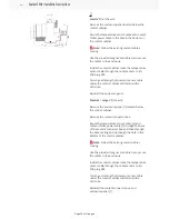
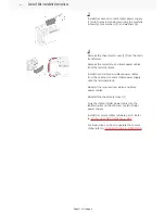
Medium / Large VF
(shown):
Remove the enclosure panel [1] located below
the control cabinet.
Remove the coolant connector box.
Route the temperature sensor cable [2] and
coolant chiller power cable [3] through the back
of the coolant connector box and then through
the base casting and up though the hole in the
bottom of the control cabinet.
Note:
Follow the existing coolant cables
routing.
Use the provided magnet and cable tie to secure
the cables to the enclosure.
Inside the control cabinet route the temperature
sensor cable through the cable carriers to I/O
PCB plug P44.
Coil any extra length of power or sensor cable
under the control cabinet and fasten with a
Velcro tie.
Reinstall the coolant connector box and
enclosure panel [1].
Coolant Chiller Installation Instructions
Page 10 of 11 pages


