094252_c_gb_hebvrr_s
haacon hebetechnik gmbh – Phone +49 (0) 9375 - 84-0 – Fax +49 (0) 9375 - 8466
3
10.2 Structure
Of the four rack support, two are powered electrically. The two passive supports can be connected mechanically
using removable connection shafts in the same way as on the manual version.
The container is to be raised evenly using this configuration.
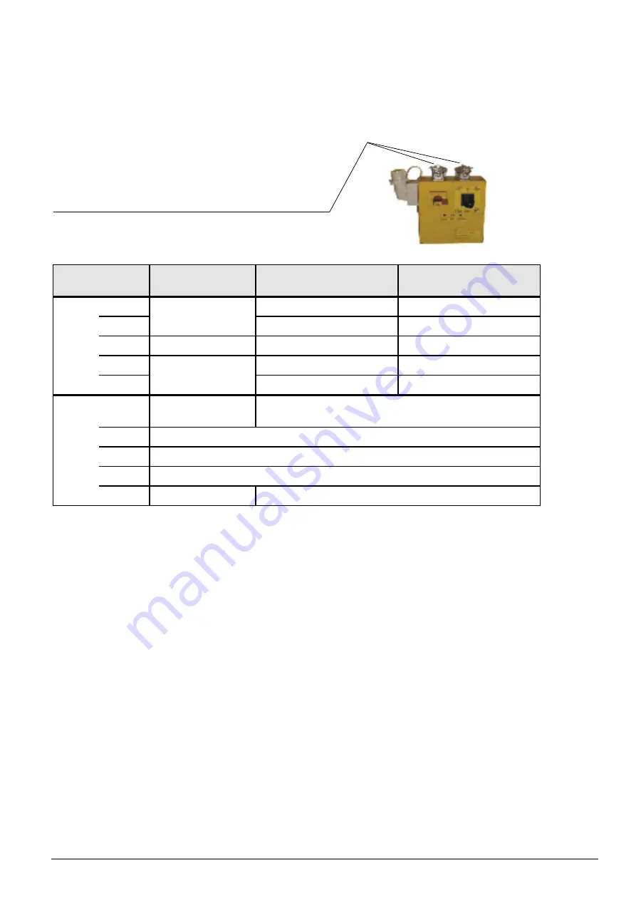
Control using the mobile controller.
Connection for motors and limit switches
The pin assignment of plug connectors A and B
(connection between the controller and the support)
is to be made as set out in the following table.
Plug Connector
Pin
24 V
Direct current
230 V
Alternating current
400 V
Alternating current
A
Motor connection
Positive pole
0 - Main motor coil
N - Main motor coil
2
L - Main motor coil
L - Main motor coil
3
-
C - Capacitor
-
4
Motor connection
Negative pole
Z - Auxiliary motor coil
L2 - Main motor coil
5
Z2 - Auxiliary motor coil
L3 - Main motor coil
B
Positive pole
24 V Fuses with A
L fused with A as a common fuse for limit switches
2
Top limit switch
3
-
4
Bottom limit switch
5
Zero Volts
Motor temperature switch
The inputs for the limit switches are isolated in floating form by two optocouplers.
For two of them the switch threshold can be set using trimmers.
The monitor the motor temperature and thus allow PTC‘s to be used as a temperature sensors.
If the system does not have a motor temperature monitor, pin B5 is to be connected in the plug with pin B (on
the 230 V and 400 V version).
Each motor has its own fuse.
To protect the semi-conductors these fuses must only be replaced with equivalent types.
On the 24 V direct current version: -0 x 38 mm, 25 A, GOULD series aM for motor circuits
- rated voltage 500 V, 20 kA switch rating
On the 230 V alternating current version: -0 x 38 mm, 0 A, GOULD series aM for motor circuits
- rated voltage 500 V, 20 kA switch rating
On the 400 V alternating current version: -0 x 38 mm, 6 A, GOULD series aM for motor circuits
- rated voltage 500 V, 20 kA switch rating
The fuses for the limit switches are also inside the controller, they measure 5 x 20 mm, A.
The controller houses a 4-way DIP switch using which the direction of rotation of the motors can be changed if
necessary.
DIP turns the first motor, DIP 2 the second.
All the components in the controller are designed for operation in temperatures as low as - 32° C. Nevertheless
in temperatures below -20°C before you start work with the controller you should check that the joystick can be
moved easily in all direction.


