background image

Convention Description 

Multi-level menus are separated by angle brackets. For example, 

File

 > 

Create

 > 

Folder


Symbols 

Convention Description 

 WARNING! 

An alert that calls attention to important information that if not understood or followed 
can result in personal injury. 

 CAUTION: 

An alert that calls attention to important information that if not understood or followed 
can result in data loss, data corruption, or damage to hardware or software.  

 IMPORTANT: 

An alert that calls attention to essential information. 

NOTE: 

An alert that contains additional or supplementary information. 

 TIP: 

An alert that provides helpful information. 


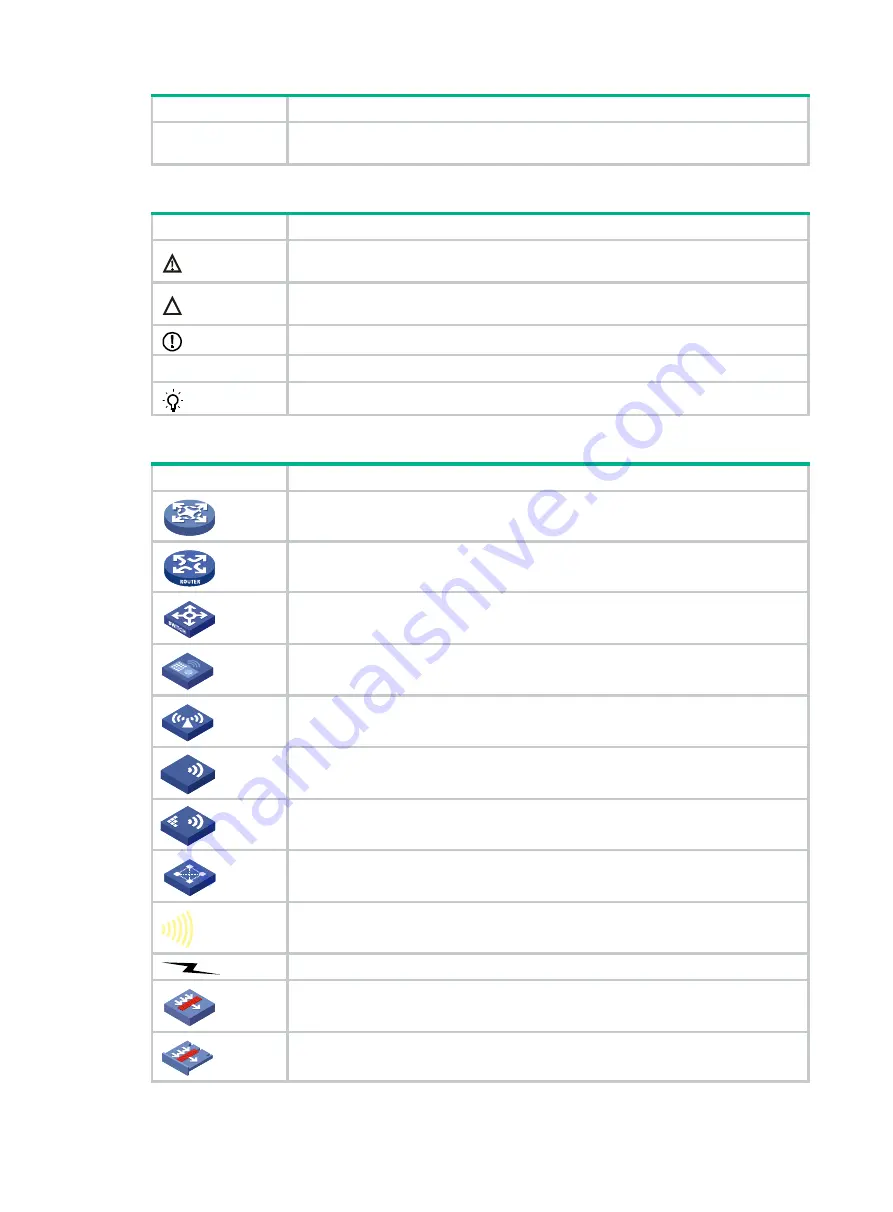
Network topology icons 

Convention Description 


Represents a generic network device, such as a router, switch, or firewall. 


Represents a routing-capable device, such as a router or Layer 3 switch. 


Represents a generic switch, such as a Layer 2 or Layer 3 switch, or a router that 
supports Layer 2 forwarding and other Layer 2 features. 


Represents an access controller, a unified wired-WLAN module, or the access 
controller engine on a unified wired-WLAN switch. 


Represents an access point. 


Wireless terminator unit. 


Wireless terminator. 


Represents a mesh access point. 


Represents omnidirectional signals. 


Represents directional signals. 


Represents a security product, such as a firewall, UTM, multiservice security 
gateway, or load balancing device. 


Represents a security module, such as a firewall, load balancing, NetStream, SSL 
VPN, IPS, or ACG module. 


T

T

T

T


Summary of Contents for WX3500H series

Page 1: ...H3C WX3500H Series Access Controllers Installation Guide New H3C Technologies Co Ltd http www h3c com hk Document version 6W103 20170519 ...

Page 2: ...ther trademarks that may be mentioned in this manual are the property of their respective owners Notice The information in this document is subject to change without notice Every effort has been made in the preparation of this document to ensure accuracy of the contents but all statements information and recommendations in this document do not constitute the warranty of any kind express or implied...

Page 3: ...u replace with actual values Square brackets enclose syntax choices keywords or arguments that are optional x y Braces enclose a set of required syntax choices separated by vertical bars from which you select one x y Square brackets enclose a set of optional syntax choices separated by vertical bars from which you select one or none x y Asterisk marked braces enclose a set of required syntax choic...

Page 4: ... topology icons Convention Description Represents a generic network device such as a router switch or firewall Represents a routing capable device such as a router or Layer 3 switch Represents a generic switch such as a Layer 2 or Layer 3 switch or a router that supports Layer 2 forwarding and other Layer 2 features Represents an access controller a unified wired WLAN module or the access controll...

Page 5: ...ocumentation To access the most up to date H3C product documentation go to the H3C website at http www h3c com hk To obtain information about installation configuration and maintenance click http www h3c com hk Technical_Documents To obtain software version information such as release notes click http www h3c com hk Software_Download Technical support service h3c com http www h3c com hk Documentat...

Page 6: ...interface cables 15 Connecting the console cable and setting terminal parameters 15 Connecting Ethernet cables 16 Installing a power module 17 Connecting an AC power cord 18 Connecting a DC power cord 18 Verifying the installation 19 Powering on the device 19 Troubleshooting 22 Power module failure 22 Symptom 22 Solution 22 No display or garbled display on the configuration terminal 22 Symptom 22 ...

Page 7: ... module views 32 AC power module 32 DC power module 33 Interface numbering 33 WX3508H 33 WX3510H 33 WX3520H and WX3540H 33 Technical specifications 34 WX3508H 34 WX3510H 34 WX3520H 35 WX3540H 35 AC power module 36 DC power module 36 Transceiver module fiber connector and optical fiber views 36 Transceiver module specifications 37 Appendix B LEDs 42 LEDs 42 LED description 44 Index 46 ...

Page 8: ...om electromagnetic interferences Make sure ESD and anti slip measures are in place Do not place the device on an unstable case or desk The device might be severely damaged in case of a fall Keep the chassis and installation tools away from walk areas Keep the chassis clean and dust free Do not place the device near water or in a damp environment Prevent water or moisture from entering the device c...

Page 9: ...ce the installation site must meet the requirements in this section Temperature and humidity Maintain the temperature and humidity in the equipment room at acceptable levels Lasting high relative humidity can cause poor insulation electricity leakage mechanical property change of materials and metal corrosion Lasting low relative humidity can cause washer contraction and ESD and bring problems inc...

Page 10: ... in an equipment room Gas Max mg m3 SO2 0 2 H2S 0 006 NH3 0 05 Cl2 0 01 NO2 0 04 Cooling The device uses left to right airflow For adequate heat dissipation make sure the following requirements are met A minimum clearance of 100 mm 3 94 in is reserved around the air vents The rack has a good ventilation system Figure 1 Airflow through the chassis WX3508H ESD prevention To prevent electrostatic dis...

Page 11: ...your wrist to maintain good contact with the skin 3 Secure the wrist strap lock and the alligator clip lock together 4 Attach the alligator clip to the rack 5 Make sure the rack is reliably grounded Figure 2 Attaching an ESD wrist strap WX3540H 1 ESD wrist strap 2 Lock 3 Alligator clip EMI All electromagnetic interference EMI sources from outside or inside of the device and application system adve...

Page 12: ... the AC power receptacle is reliably grounded Install a lightning protector at the input end of the power module to enhance the lightning protection capability of the power supply Installation accessories The installation accessories vary by device model Table 4 describes the installation accessories available for the access controllers Table 4 Installation accessories for the access controllers A...

Page 13: ...nd outlet vents for heat dissipation of the device chassis A good ventilation system is available at the installation site Temperature 0 C to 45 C 32 F to 113 F Humidity 5 RH to 95 RH noncondensing Cleanliness Dust concentration 3 10 4 particles m 3 No dust on desk within three days ESD prevention The equipment and rack or workbench are reliably grounded The equipment room is dust proof The humidi...

Page 14: ...cted power strip is available Electricity safety A UPS is available The power off switch in the equipment room is identified and accessible so that the power can be immediately shut off when an accident occurs Rack mounting requirements The rack has a good ventilation system The rack is sturdy enough to support the weight of the device and installation accessories The size of the rack is appropria...

Page 15: ... you want to open the chassis contact H3C Support for permission Otherwise H3C will not be liable for any consequence caused thereby Confirming installation preparations Before you install the device verify that you have read Preparing for installation carefully and the installation site meets all the requirements ...

Page 16: ...Installation flow Mounting the device on a workbench CAUTION Do not place heavy objects on the device If a standard 19 inch rack is not available you can mount the device on a clean flat workbench To mount the device on a workbench ...

Page 17: ... inch rack IMPORTANT Keep a minimum distance of 1 U 44 45 mm or 1 75 in between devices in a rack for good heat dissipation Mounting brackets The available mounting brackets vary by device model Table 6 describes the mounting brackets available for the access controllers Table 6 Mounting brackets available for the access controllers Device model Mounting bracket WX3508H WX3510H WX3520H WX3540H Mou...

Page 18: ...g cage nuts 2 Use the screws supplied with the mounting brackets to secure the mounting brackets to both sides of the device Figure 7 Installing the mounting brackets WX3508H 3 Supporting the device bottom with one hand and holding the device front with the other place the device gently in the rack Use M6 rack screws to attach the mounting brackets on the device to the front rack posts ...

Page 19: ...ground the device 1 Use a Phillips screwdriver to remove the grounding screw from the chassis 2 Use the grounding screw to attach the ring terminal of the grounding cable to the chassis 3 Connect the other end of the grounding cable according to the grounding method you use Grounding the device with a grounding strip If a grounding strip is available at the installation site connect the other end ...

Page 20: ...grounding strip WX3508H Grounding the device with the rack Connect the other end of the grounding cable to the grounding point on the rack and make sure the rack has been reliably grounded Figure 10 Grounding the device with the rack WX3508H ...

Page 21: ...oors install a network port lightning protector for the port to protect against damages caused by lightning strikes No network port lightning protectors are provided with the device Purchase them yourself as required To install a network port lightning protector for a network port 1 Use a double faced adhesive tape to stick the network port lightning protector onto the device chassis and make sure...

Page 22: ...if required To use a surge protected power strip first connect the AC power line routed from outdoors to the strip and then connect the power cord from the device to the strip You can attach the surge protected power strip to the rack workbench or wall of the equipment room Connecting interface cables Connecting the console cable and setting terminal parameters To configure and manage the device t...

Page 23: ...ptical fiber must be not less than 100 mm 3 94 in Keep the fiber end clean Make sure the Tx and Rx ports on a transceiver module are connected to the Rx and Tx ports on the peer end respectively No transceiver modules are provided with the device Purchase transceiver modules yourself as required For transceiver module specifications see Appendix A Chassis views and technical specifications The fib...

Page 24: ...want to install a power module with a Phillips screwdriver Keep the remove blank filler panel for future use 2 Holding the handle of the power module with one hand and supporting the bottom of the power module with another hand push the power module into the slot along the guide rails until the power module is completely inserted 3 Use a Phillips screwdriver to fasten the screws on the power modul...

Page 25: ...n the device 3 Pivot the bail latch rightwards to secure the power cord 4 Connect the other end of the AC power cord to the AC power source Figure 16 Connecting an AC power cord WX3540H Connecting a DC power cord 1 Use a flat blade screwdriver to remove the protection cover from the DC power module 2 Correctly insert the DC plug into the DC power receptacle 3 Use a flat blade screwdriver to fasten...

Page 26: ...Powering on the device This section uses the WX3510H access controller as an example 1 Power on the device The device initializes its memory and runs the BootWare The following information appears on the terminal screen System is starting Press Ctrl D to access BASIC BOOTWARE MENU Press Ctrl T to start heavy memory test Booting Normal Extended BootWare The Extended BootWare is self decompressing D...

Page 27: ...SHA224 passed Known answer test for SHA256 passed Known answer test for SHA384 passed Known answer test for SHA512 passed Known answer test for HMAC SHA1 passed Known answer test for HMAC SHA224 passed Known answer test for HMAC SHA256 passed Known answer test for HMAC SHA384 passed Known answer test for HMAC SHA512 passed Known answer test for AES passed Known answer test for RSA signature verifi...

Page 28: ...Algorithms Known Answer Tests passed Line con0 is available Press ENTER to get started 3 Press Enter at the prompt and you can configure the device when the prompt H3C appears During the startup process the CPLD is automatically upgraded to the latest version ...

Page 29: ...display on the configuration terminal Symptom The configuration terminal does not have display or have a garbled display when the device is powered on Solution To resolve the issue 1 Verify that the power system is operation correctly 2 Verify that the console cable is connected correctly to the specified serial port on the configuration terminal 3 Verify that the following settings are configured...

Page 30: ... HyperTerminal to check for errors If an error exists correct the error For example check for the following errors that might occur When you use XMODEM to load software you select a baud rate other than 9600 bps but you have not reset the baud rate for the HyperTerminal When you use TFTP to load software you entered an incorrect IP address software name or TFTP serve path When you use FTP to load ...

Page 31: ...boot reason User soft reboot Boot image cfa0 boot bin Boot image version 7 1 064 Release 5323 Compiled Mar 21 2017 16 00 00 System image cfa0 system bin System image version 7 1 064 Release 5323 Compiled Mar 21 2017 16 00 00 Slot 1 Uptime is 0 week 2 days 0 hour 57 minutes with 1 1000MHz Multi core Processor 4064M bytes DDR3 16M bytes NorFlash Memory 4002M bytes CFCard Memory Hardware Version is V...

Page 32: ... the device Details not shown H3C display diagnostic information Save or display diagnostic information Y save N display Y N n display clock 09 36 55 UTC Thu 04 20 2017 display version H3C Comware Software Version 7 1 064 Release 5323 Copyright c 2004 2017 New H3C Technologies Co Ltd All rights reserved H3C WX3510H uptime is 0 weeks 0 days 18 hours 28 minutes Last reboot reason User soft reboot Bo...

Page 33: ...ation including the serial number manufacturing date MAC address and vendor name Use the display device manuinfo command to display the electronic label data for the device H3C display device manuinfo Slot 1 CPU 0 DEVICE_NAME WX3510H DEVICE_SERIAL_NUMBER 210235A1JNC14B900031 MAC_ADDRESS 000f e212 6103 MANUFACTURING_DATE 2017 03 23 VENDOR_NAME H3C Table 8 Command output Field Description DEVICE_NAM...

Page 34: ... memory Memory statistics are measured in KB Slot 1 Total Used Free Shared Buffers Cached FreeRatio Mem 3775116 1042200 2732916 0 160 194828 72 4 Buffers Cache 847212 2927904 Swap 0 0 0 Table 10 Command output Field Description Slot x IRF member device ID of the device Mem Memory usage information Total Total size of the physical memory space that can be allocated Used Used physical memory Free Fr...

Page 35: ...he CLI You can remotely reboot the device in either of the following ways Reboot the device immediately by using the reboot command Schedule a reboot to occur at a specific time or date or after a delay by using the schedule reboot command Power off and power on the device This method cuts off the power of the device forcibly which might cause data loss It is the least preferred method Restriction...

Page 36: ... immediately Task Command Remarks Reboot the device immediately reboot force Available in user view Scheduling a reboot for the device Task Command Remarks Schedule a reboot Schedule a reboot to occur at a specific time or date schedule reboot at time date Schedule a reboot to occur after a delay schedule reboot delay time Use either command By default no reboot date or time or reboot delay time i...

Page 37: ...sing Ethernet copper ports 7 and 8 combo interfaces 3 1000BASE X SFP ports 7 and 8 combo interfaces 4 USB port 5 SD card slot 6 Console port Figure 19 Rear panel 1 AC power receptacle 2 Grounding screw WX3510H Figure 20 Front panel 1 100 1000BASE T autosensing Ethernet copper ports 1 through 8 combo interfaces 2 100BASE FX 1000BASE X SFP ports 1 through 8 combo interfaces 3 Console port ...

Page 38: ... Figure 22 Front panel 1 100 1000BASE T autosensing Ethernet copper ports 1 through 8 combo interfaces 2 100BASE FX 1000BASE X SFP ports 1 through 8 combo interfaces 3 10GBASE R SFP ports 9 and 10 4 Console port Figure 23 Rear panel 1 Power module slot 1 PWR1 2 Power module slot 2 PWR2 3 Expansion slot 4 Grounding screw ...

Page 39: ... X SFP ports 1 through 8 combo interfaces 3 10GBASE R SFP ports 9 and 10 4 100 1000BASE T management Ethernet port 5 Console port Figure 25 Rear panel 1 Power module slot 1 PWR1 2 Power module slot 2 PWR2 3 Expansion slot 4 Grounding screw Power module views AC power module Figure 26 AC power module 1 Captive screw 2 Power receptacle ...

Page 40: ...interfaces GigabitEthernet 1 0 7 and GigabitEthernet 1 0 8 with 1000BASE X SFP ports marked 7 and 8 respectively WX3510H 100 1000BASE T autosensing Ethernet copper ports marked 1 through 8 form combo interfaces GigabitEthernet 1 0 1 through GigabitEthernet 1 0 8 with 100BASE FX 1000BASE X SFP ports marked 1 through 8 respectively WX3520H and WX3540H Fixed ports on the WX3520H and WX3540H access co...

Page 41: ...Weight 2 kg 4 41 lb Operating temperature 0 C to 45 C 32 F to 113 F Operating humidity 5 RH to 95 RH noncondensing WX3510H Table 14 WX3510H technical specifications Item Specification Console port One 9600 bps default to 115200 bps Gigabit Ethernet port 8 100 1000BASE T autosensing Ethernet copper port SFP port 8 100BASE FX 1000BASE X SFP port Memory 2 2GB DDR3 Storage media 4GB CF Card Dimensions...

Page 42: ...C to 45 C 32 F to 113 F Operating humidity 5 RH to 95 RH noncondensing WX3540H Table 16 WX3540H technical specifications Item Specification Console port One 9600 bps default to 115200 bps Gigabit Ethernet port 8 100 1000BASE T autosensing Ethernet copper port Management Ethernet port 1 100 1000BASE T management Ethernet port SFP port 8 100BASE FX 1000BASE X SFP port SFP port 2 10GBASE R SFP port M...

Page 43: ...0 W DC power module Table 18 DC power module specifications Item Specifications Model PSR150 D1 Rated input voltage range 48 VDC to 60 VDC Rated power capacity 150 W Transceiver module fiber connector and optical fiber views To connect a fiber port on the device use an SFP or SFP transceiver module and an optical fiber with LC connectors Figure 28 SFP transceiver module ...

Page 44: ...modules WX3508H SFP GE SX MM850 A see Table 23 SFP GE LX SM1310 A seeTable 21 SFP GE LH40 SM1310 see Table 25 SFP GE LH40 SM1550 see Table 26 SFP GE LH70 SM1550 see Table 27 WX3510H WX3520H WX3540H SFP FE SX MM1310 A see Table 20 SFP FE LX SM1310 A see Table 21 SFP FE LH40 SM1310 see Table 22 SFP GE SX MM850 A see Table 23 SFP GE LX SM1310 A see Table 24 SFP GE LH40 SM1310 see Table 25 SFP GE LH40...

Page 45: ...ons Item Specification Central wavelength 1310 nm Transmission distance 15 km 9 32 miles Transmission rate 125 Mbps Connector type Duplex LC Fiber mode SMF Fiber diameter 9 µm Transmit power 15 to 8 dBm Receive sensitivity 28 dBm Saturation 7 dBm Table 22 SFP FE LH40 SM1310 specifications Item Specification Central wavelength 1310 nm Transmission distance 40 km 24 86 miles Transmission rate 125 Mb...

Page 46: ...s Item Specification Central wavelength 1310 nm Transmission distance 10 km 6 21 miles Transmission rate 1250 Mbps Connector type Duplex LC Fiber mode SMF Fiber diameter 9 µm Transmit power 9 5 to 3 dBm Receive sensitivity 20 dBm Saturation 3 dBm Table 25 SFP GE LH40 SM1310 specifications Item Specification Central wavelength 1310 nm Transmission distance 40 km 24 86 miles Transmission rate 1250 M...

Page 47: ...Item Specification Central wavelength 1550 nm Transmission distance 70 km 43 50 miles Transmission rate 1250 Mbps Connector type Duplex LC Fiber mode SMF Fiber diameter 9 µm Transmit power 4 to 5 dBm Receive sensitivity 22 dBm Saturation 3 dBm Table 28 SFP XG SX MM850 A specifications Item Specification Central wavelength 850 nm Transmission distance 300 m 984 25 ft Transmission rate 10 3125 Gbps ...

Page 48: ...tem Specification Central wavelength 1310 nm Transmission distance 10 km 6 21 miles Transmission rate 10 3125 Gbps Connector type Duplex LC Fiber mode SMF Fiber diameter 9 µm Transmit power 8 2 to 0 5 dBm Receive sensitivity 14 4 dBm Saturation 0 5 dBm Table 31 SFP XG LH40 SM1550 specifications Item Specification Central wavelength 1550 nm Transmission distance 40 km 24 86 miles Transmission rate ...

Page 49: ...SE X SFP port status LEDs 3 System status LED SYS Figure 32 WX3510H LEDs 1 100 1000BASE T autosensing Ethernet copper port status LEDs 2 100BASE FX 1000BASE X SFP port status LEDs 3 Power module 1 status LED PWR1 4 Power module 2 status LED PWR2 5 System status LED SYS 6 Expansion card status LED MOD 2 3 1 1 2 3 4 5 6 ...

Page 50: ... LED PWR2 6 System status LED SYS 7 Expansion card status LED MOD Figure 34 WX3540H LEDs 1 100 1000BASE T autosensing Ethernet copper port status LEDs 2 100BASE FX 1000BASE X SFP port status LEDs 3 10GBASE R SFP port status LEDs 4 100 1000BASE T out of band management Ethernet port status LED LINK ACT 5 Power module 1 status LED PWR1 6 Power module 2 status LED PWR2 7 System status LED SYS 8 Expan...

Page 51: ...nt on the port Flashing green The port is receiving or transmitting data at 1000 Mbps Off No link is present on the port Table 33 LED description for the WX3510H WX3520H WX3540H access controllers LED Mark Status Description Power module 1 status LED PWR1 Steady green Power module 1 is operating correctly Steady yellow Power module 1 is faulty Off No power module is present Power module 2 status L...

Page 52: ...present on the port Flashing green The port is receiving or transmitting data at 1000 Mbps Off No link is present on the port 100BASE FX 1000B ASE X SFP port status LED N A Steady yellow A 100 Mbps link is present on the port Flashing yellow The port is receiving or transmitting data at 100 Mbps Steady green A 1000 Mbps link is present on the port Flashing green The port is receiving or transmitti...

Page 53: ...y on switching engine 26 fiber port connection 16 grounding 12 information display on controller engine 26 information display on switching engine 26 installation verification 19 management and maintenance 24 memory usage display 27 operational statistics 24 power supply operating state 28 powering on 19 rack installation 10 rebooting 28 troubleshooting 22 workbench device mount 9 displaying built...

Page 54: ...tallation site requirements 2 I installing AC 8 AC installation flow 9 checklist 6 cooling requirements 3 device in rack 10 EMI prevention 4 ESD prevention 3 installation verification 19 lightning protection 5 site cleanliness 2 site examination 2 site humidity 2 site temperature 2 L lightning protection 5 M maintaining hardware maintenance 24 managing hardware management 24 memory usage display 2...

Page 55: ...re loading failure 23 verifying installation 19 R rack device installation 10 rebooting the device 28 S safety caution and warning symbols 1 device grounding 12 electrical safety recommendations 1 EMI prevention 4 ESD prevention 3 general recommendations 1 installation site cleanliness 2 installation site dust concentration 2 installation site gas saturation 2 installation site humidity 2 installa...

Page 56: ...49 software loading failure 23 V ventilation installation site 3 verifying installation 19 W workbench device mount 9 ...

Reviews: