background image

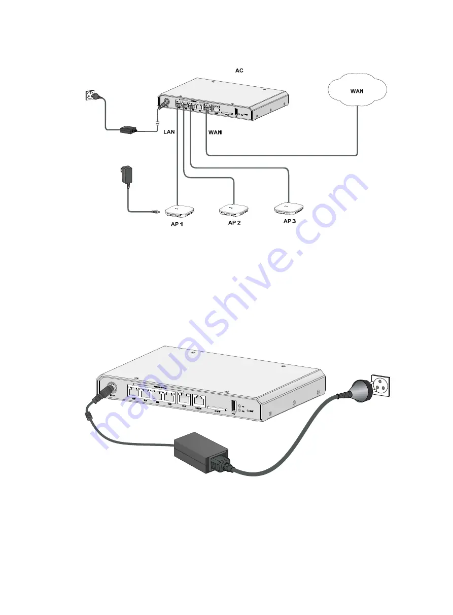
Figure 5 Connecting the device to the network 


Connecting the power adapter 

1. 

Make sure the device is reliably grounded. 

2. 

Connect the power adapter to the external power source. 

3. 

Connect the DC power plug of the power adapter to the DC power receptacle on the front panel 
of the device. 

Figure 6 Connecting the power adapter 


Verifying the installation 

Before powering on the device, verify the following information:  


Enough clearance is reserved around the device for heat dissipation. 


The power source has the specifications required by the device. 

Summary of Contents for WX2510H

Page 1: ...H3C WX2510H Access Controller Installation Guide New H3C Technologies Co Ltd http www h3c com hk Document version 6W101 20170414...

Page 2: ...her trademarks that may be mentioned in this manual are the property of their respective owners Notice The information in this document is subject to change without notice Every effort has been made i...

Page 3: ...hat you replace with actual values Square brackets enclose syntax choices keywords or arguments that are optional x y Braces enclose a set of required syntax choices separated by vertical bars from wh...

Page 4: ...topology icons Convention Description Represents a generic network device such as a router switch or firewall Represents a routing capable device such as a router or Layer 3 switch Represents a generi...

Page 5: ...cumentation To access the most up to date H3C product documentation go to the H3C website at http www h3c com hk To obtain information about installation configuration and maintenance click http www h...

Page 6: ...Verifying the installation 8 Starting the device 9 Troubleshooting 10 Power failure 10 Symptom 10 Solution 10 Software loading failure 10 Symptom 10 Solution 10 Hardware management and maintenance 11...

Page 7: ...ver to fasten screws Perform the following tasks to prevent condensation Unpack the device a minimum of half an hour after you move the device from a location below 0 C 32 F to the equipment room Powe...

Page 8: ...humidity 0 C to 45 C 32 F to 113 F 5 to 95 noncondensing Cleanliness Dust buildup on the chassis might result in electrostatic adsorption which causes poor contact of metal components and contact poi...

Page 9: ...sed use a single phase three wire power receptacle with protection earth PE to filter interference from the power grid Keep the device far away from radio transmitting stations radar stations and high...

Page 10: ...rotect the power system from the power grid system The protection ground of the device is separated from the grounding device or lightning protection grounding device as far as possible The device is...

Page 11: ...therwise H3C will not be liable for any consequence caused thereby Confirming installation preparations Before you install the device verify that you have read Preparing for installation carefully and...

Page 12: ...rod To ground the device use a grounding cable to connect the device to a grounding strip Attaching the ring terminal to the grounding cable The device is not provided with a grounding cable but a rin...

Page 13: ...t the other end of the grounding cable to the grounding strip and make sure the grounding strip has been reliably grounded Figure 4 Grounding the device with a grounding strip Connecting the device to...

Page 14: ...urce 3 Connect the DC power plug of the power adapter to the DC power receptacle on the front panel of the device Figure 6 Connecting the power adapter Verifying the installation Before powering on th...

Page 15: ...ompt within 4 seconds to access the Boot menu Otherwise the system enters the system image file reading and self compressing process To access the Boot menu after the system enters the system image fi...

Page 16: ...y and correctly If a port is not connected securely reconnect the port and make sure the connections are correct 2 View the software loading process displayed on the HyperTerminal to check for errors...

Page 17: ...bin Boot image version 7 1 064 ESS 5117 Compiled Apr 10 2017 16 00 00 System image flash wx2510h cmw710 system e5107 bin System image version 7 1 064 ESS 5117 Compiled Apr 10 2017 16 00 00 with 1 ARM...

Page 18: ...erved H3C WX2510H uptime is 0 weeks 1 day 17 hours 4 minutes Last reboot reason User soft reboot Displaying detailed information about the device Use the display device verbose command to display deta...

Page 19: ...Average CPU usage in the last 5 seconds after the device boots the device calculates and records the average CPU usage at the interval of 5 seconds 3 in last 1 minute Average CPU usage in the last mi...

Page 20: ...fter a delay by using the schedule reboot command Power off and power on the device This method cuts off the power of the device forcibly which might cause data loss It is the least preferred method R...

Page 21: ...edule a reboot Schedule a reboot to occur at a specific time or date schedule reboot at time date Schedule a reboot to occur after a delay schedule reboot delay time Use either command By default no r...

Page 22: ...T Figure 8 Rear panel 1 Grounding screw Technical specifications Table 9 Technical specifications Item Specification Console port One 9600 bps default to 115200 bps Gigabit Ethernet port 5 100 1000BAS...

Page 23: ...e four PoE ports provide the max PoE power concurrently Weight 0 9 kg 1 98 lb Operating temperature 0 C to 45 C 32 F to 113 F Relative humidity noncondensing 5 to 95 Interface arrangement The device p...

Page 24: ...eady yellow A 100 Mbps link is present on the port Flashing yellow The port is receiving or transmitting data at 100 Mbps Off No link is present on the port PoE system status PoE PoE Steady on A PoE p...

Page 25: ...tics for the device 11 Displaying software and hardware version information for the device 11 Displaying the CPU usage of the device 13 Displaying the electronic label data for the device 12 Displayin...

Reviews: