background image


Installation tools 

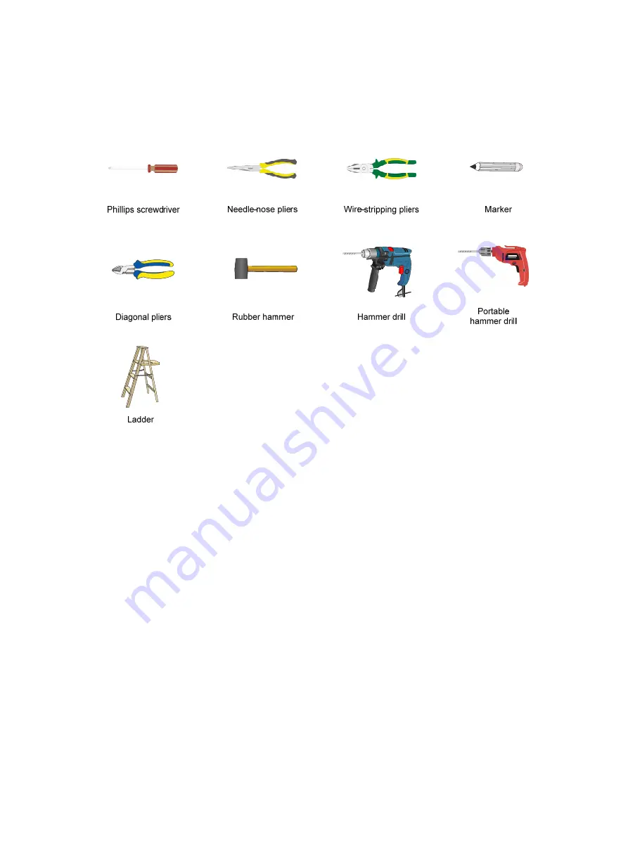
When installing the AP, you might need the following tools. Prepare the installation tools as 
required. 

Figure 2 Installation tools 


Summary of Contents for WA538

Page 1: ...H3C WA538 Access Point Installation Guide New H3C Technologies Co Ltd http www h3c com Document version 6W102 20190527 ...

Page 2: ...r respective owners Notice The information in this document is subject to change without notice All contents in this document including statements information and recommendations are believed to be accurate but they are presented without warranty of any kind express or implied H3C shall not be liable for technical or editorial errors or omissions contained herein Environmental protection This prod...

Page 3: ... are optional x y Braces enclose a set of required syntax choices separated by vertical bars from which you select one x y Square brackets enclose a set of optional syntax choices separated by vertical bars from which you select one or none x y Asterisk marked braces enclose a set of required syntax choices separated by vertical bars from which you select a minimum of one x y Asterisk marked squar...

Page 4: ...as a Layer 2 or Layer 3 switch or a router that supports Layer 2 forwarding and other Layer 2 features Represents an access controller a unified wired WLAN module or the access controller engine on a unified wired WLAN switch Represents an access point Represents a wireless terminator unit Represents a wireless terminator Represents a mesh access point Represents omnidirectional signals Represents...

Page 5: ...Documentation feedback You can e mail your comments about product documentation to info h3c com We appreciate your comments ...

Page 6: ...etermining the installation position 3 Installing the AP 4 Mounting the AP on a wall 4 Mounting the AP on a ceiling 7 Connecting the AP to the power source 8 Check before power on 8 Connecting the PoE power supply 8 Connecting the local power supply 9 PoE injector power supply 10 Check after power on 10 Connecting the AP to the network 10 Appendix A Technical specifications 12 Appendix B Ports and...

Page 7: ...tion Take adequate safety measures to avoid body injury and device damage Place the AP in a dry and flat location and take anti slip measures Keep the AP clean and dust free Do not place the AP in a moist area and avoid liquid intrusion Keep the AP and installation tools away from walkways Temperature and humidity requirements Table 1 Temperature and humidity requirements Item Specification Operat...

Page 8: ...2 Installation tools When installing the AP you might need the following tools Prepare the installation tools as required Figure 2 Installation tools ...

Page 9: ...etermine the installation position by observing the following principles Few obstacles such as wall exist between the AP and clients The AP is far away from electronic devices such as microwave oven that might generate radio frequency RF noise The AP does not hinder people s daily work and life The place is not water seeping water soaking and condensing The AP is more than 5 m 16 40 ft away from 3...

Page 10: ...acket to the AP and the wall ceiling bracket to the wall or ceiling Figure 4 Mounting bracket kit 1 AP bracket 2 Alignment peg 3 Wall Ceiling bracket 4 Installation hole Figure 5 Wall Ceiling bracket installation holes Mounting the AP on a wall 1 Set the alignment pegs on the AP bracket into the alignment holes in the AP rear Use the M4 7 screw to secure the AP bracket to the AP through the instal...

Page 11: ...holes on the wall by using the wall ceiling bracket as shown in Figure 7 Figure 7 Marking installation holes on the wall 3 Drill holes with a diameter of 6 mm 0 24 in and a depth of 30 mm 1 18 in in the marked locations as shown in Figure 8 Figure 8 Drilling holes in the wall ...

Page 12: ...ket with the anchors and insert screws through the installation holes into the screw anchors Adjust the position of the wall ceiling bracket and fasten the screws Figure 10 Attaching the wall ceiling bracket to the wall 6 Align the two tabs on the AP bracket into the notches on the wall ceiling bracket and then rotate the AP clockwise until it snaps into place as shown in Figure 11 Figure 11 Attac...

Page 13: ...e installation holes on the ceiling by using the wall ceiling bracket 3 Drill two holes with a diameter of 5 mm 0 20 in in the marked positions as shown in Figure 12 Figure 12 Drilling holes in the ceiling 4 Thread the pan head screws through the installation holes in the wall ceiling bracket and into holes in the ceiling Fasten washers and nuts at the other side of the ceiling to attach the wall ...

Page 14: ...ly is reliably grounded To power the AP through PoE make sure the PoE power supply PSE is reliably grounded To power the AP through PoE injector make sure the PoE power supply PSE is reliably grounded AP is to be connected only to PoE networks without routing to the outside plant Connecting the PoE power supply CAUTION To use both Ethernet ports on the AP connect an Ethernet cable to one port for ...

Page 15: ...wer adapter specifications Item Specification Input 100 VAC to 240 VAC Output 54 VDC at 0 74 A You can power the AP by using an power adapter Use the power adapter to connect the power port of the AP to the local power source Connect the power adapter to the H3C WA538 as shown in Figure 16 Figure 16 Connecting the local power supply ...

Page 16: ...tion about AP LEDs see Appendix B Ports and LEDs Connecting the AP to the network For Internet or MAN access connect an Ethernet port on the AP to an Ethernet port on an Ethernet switch and then verify that the AP has been connected to the network All AP settings are configured on the AC when the AP operates as a fit AP Execute the display wlan ap all command on the AC If the AP status is R M the ...

Page 17: ...Server AP licenses 0 Remaining local AP licenses 127 Sync AP licenses 0 AP information State I Idle J Join JA JoinAck IL ImageLoad C Config DC DataCheck R Run M Master B Backup AP name APID State Model Serial ID ap1 1 R M WA538 219801A1NN9182032213 ...

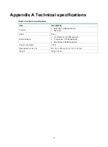
Page 18: ...m H3C WA538 Protocol IEEE 802 11a b g n ac Wave2 802 3at af Radio Three Built in antenna 2 4 G antenna 5 30 dBi peak gain 5 G antenna 7 50 dBi peak gain ble antenna 5 02 dBi peak gain Power consumption 25 W Dimensions H W D 40 183 183 mm 1 57 7 20 7 20 in Weight 700 g 1 54 lb ...

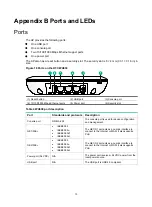
Page 19: ...able 4 WA538 port description Port Standards and protocols Description Console port RS EIA 232 The console port is used for device configuration and management GE1 PoE IEEE802 3 IEEE802 3u IEEE802 3af IEEE802 3at The GE1 0 1 port acts as an uplink interface to connect to the Internet or MAN It also supports PoE GE2 PoE IEEE802 3 IEEE802 3u IEEE802 3af IEEE802 3at The GE1 0 2 port acts as an uplink...

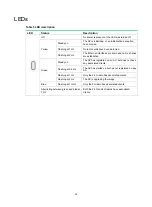
Page 20: ...faces are down and no mesh links are established Green Steady on The AP has registered on an AC but does not have any associated clients Flashing at 0 5 Hz The AP has started up but has not registered on any AC Flashing at 1 Hz Only the 2 4G radio has associated clients Flashing at 2 Hz The AP is upgrading the image Blue Flashing at 1 GHz Only the 5G radio has associated clients Alternating betwee...

Reviews: