11
•
Install a lightning protector at the input end of the power supply to enhance lightning protection
capability. For how to install a lightning protector, see "
Connecting the AC power supply to a
power strip with lightning protection
."
Rack installation
•
Reserve at least 1 m (3.28 ft) of clearance between the rack and walls or other UTM devices.
•
Reserve at least 10 cm (3.94 in) of clearance at the air inlet and exhaust vents for ventilation.
•
The equipment room is at least 3 m (9.84 ft) high and an air conditioner is installed.
Power supply
Make sure the power source of the installation site is steady and can satisfy the input requirements of
the power modules and parameters such as rated voltage. For power module specifications, see "
Power
input
."
Installation tools
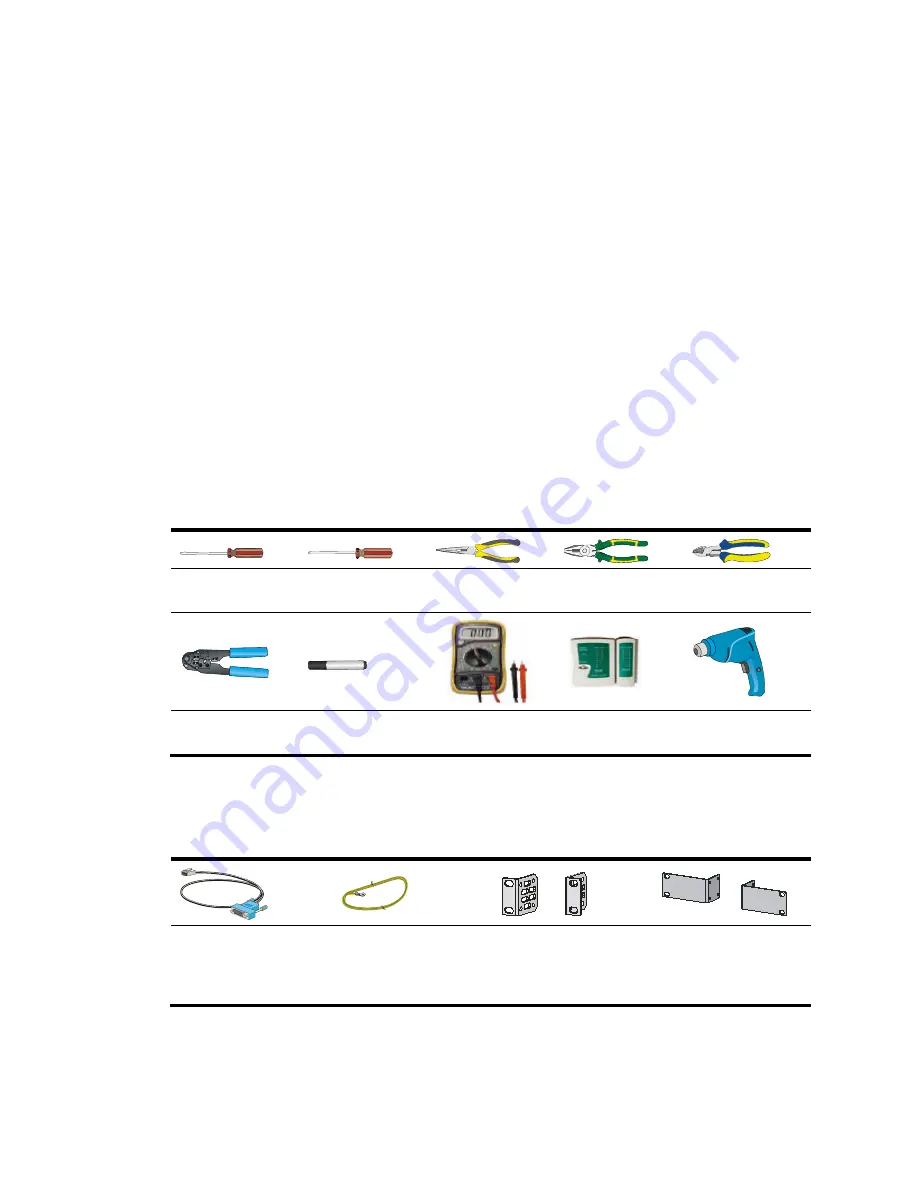
The tools in the table may be used for installing the UTM device. Prepare them yourself.
Flat-blade
screwdriver
Phillips screwdriver Needle-nose pliers
Wire-stripping
pliers
Diagonal pliers
RJ-45 crimping
pliers
Marker Multimeter
Network cable
tester
Hot air blowing
gun
Accessories
Console cable (supplied
with UTM device)
Grounding cable
(supplied with UTM
device)
U200-A and U200-M
front mounting brackets
(supplied with UTM
device)
U200-S mounting
brackets (supplied with
UTM device)


