


17-21
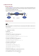
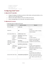
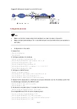
Figure 17-10
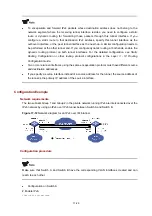
Network diagram for an ISATAP tunnel
Configuration procedure
z
Make sure that the corresponding VLAN interfaces have been created on the switch.
z
Make sure that VLAN-interface 101 on the ISATAP switch and the ISATAP host are reachable to
each other.
z
Configuration on the switch
# Enable IPv6.
<Switch> system-view
[Switch] ipv6
# Configure addresses for interfaces.
[Switch] interface vlan-interface 100
[Switch-Vlan-interface100] ipv6 address 3001::1/64
[Switch-Vlan-interface100] quit
[Switch] interface vlan-interface 101
[Switch-Vlan-interface101] ip address 1.1.1.1 255.0.0.0
[Switch-Vlan-interface101] quit
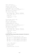
# Configure an ISATAP tunnel.
[Switch] interface tunnel 0
[Switch-Tunnel0] ipv6 address 2001::5efe:0101:0101 64
[Switch-Tunnel0] source vlan-interface 101
[Switch-Tunnel0] tunnel-protocol ipv6-ipv4 isatap
# Disable the RA suppression so that hosts can acquire information such as the address prefix from
the RA message released by the ISATAP switch.
[Switch-Tunnel0] undo ipv6 nd ra halt
[Switch-Tunnel0] quit
# Create service loopback group 1 to support the tunnel service.
[Switch] service-loopback group 1 type tunnel
# Add GigabitEthernet 1/0/3 to service loopback group 1.
[Switch] interface GigabitEthernet 1/0/3
[Switch-GigabitEthernet1/0/3] undo stp enable
[Switch-GigabitEthernet1/0/3] port service-loopback group 1
[Switch-GigabitEthernet1/0/3] quit