


17-12
Configuration Example
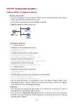
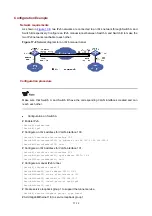
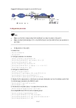
Network requirements
As shown in
, two IPv6 networks are connected to an IPv4 network through Switch A and
Switch B respectively. Configure an IPv6 manual tunnel between Switch A and Switch B to make the
two IPv6 networks reachable to each other.
Figure 17-8
Network diagram for an IPv6 manual tunnel
Configuration procedure
Make sure that Switch A and Switch B have the corresponding VLAN interfaces created and can
reach each other.
z
Configuration on Switch A
# Enable IPv6.
<SwitchA> system-view
[SwitchA] ipv6
# Configure an IPv4 address for VLAN-interface 100.
[SwitchA] interface vlan-interface 100
[SwitchA-Vlan-interface100] ip address 192.168.100.1 255.255.255.0
[SwitchA-Vlan-interface100] quit
# Configure an IPv6 address for VLAN-interface 101.
[SwitchA] interface vlan-interface 101
[SwitchA-Vlan-interface101] ipv6 address 3002::1 64
[SwitchA-Vlan-interface101] quit
# Configure a manual IPv6 tunnel.
[SwitchA] interface tunnel 0
[SwitchA-Tunnel0] ipv6 address 3001::1/64
[SwitchA-Tunnel0] source vlan-interface 100
[SwitchA-Tunnel0] destination 192.168.50.1
[SwitchA-Tunnel0] tunnel-protocol ipv6-ipv4
[SwitchA-Tunnel0] quit
# Create service loopback group 1 to support the tunnel service.
[SwitchA] service-loopback group 1 type tunnel
# Add GigabitEthernet 1/3 to service loopback group 1.