1-4
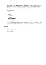
*+3 UP 1 2 DIS -- -- 000f-cbb8-1a82
--------------------------------------------------------------------------
* indicates the device is the master.
+ indicates the device through which the user logs in.
The above information indicates following:
z
On device 1, IRF port 1 is aggregated from physical IRF ports 1 and 2, and it is down; IRF port 2 is
aggregated from physical IRF ports 3 and 4, and it is up.
z
On device 2, IRF port 1 is aggregated from physical IRF ports 1 and 2, and it is up; IRF port 2
corresponds to physical IRF port 3, and it is up.
z
On device 3, IRF port 1 corresponds to physical IRF port 1, and it is up; IRF is disabled on IRF port
2.
z
IRF port 1 of device 1 does not connect with any other device; IRF port 2 of device 1 connects to
IRF port 1 of device 2; IRF port 2 connects to IRF port 1 of device 3; IRF port 2 of device 3 does not
connect with any other device.
z
All the three devices belong to one IRF virtual device . The bridge MAC address of the master is
000f-cbb8-1a82.
Network topology view is as shown in
Figure 1-1
Network topology view
2
1
Device 1
4
Device 2
2
4
3
Device 3
1
3
2
4
3
1
Link aggregation
Table 1-3 display irf topology
command output description
Field
Description
Switch
Member ID
z
The ID with * indicates that the device is the master;
z
The ID with + indicates t that it is the device that you are working on.
IRF-Port 1
Information of IRF port 1, including link (link state), member (corresponding
physical port), and neighbor.
IRF-Port 2
Information of IRF port 2, including link, member, and neighbor.
BelongTo
The IRF that the device belongs to, represented by the IRF CPU MAC address.
Link
Link state of the IRF port:
z
UP
z
DOWN
z
ISOLATE: The corresponding physical IRF port is isolated because it cannot
meet the requirement of the IRF. The reason may be that the physical IRF
port connects to a non-S5500-EI device, or the IRF port of the peer end is not
connected according to the port serial numbers.


