


2-19
2.
Attach the power cord retainer clip (supplied with the power supply) into the two holes next to
the AC-input power receptacle on the power supply, and pull the retainer clip leftwards (see
3.
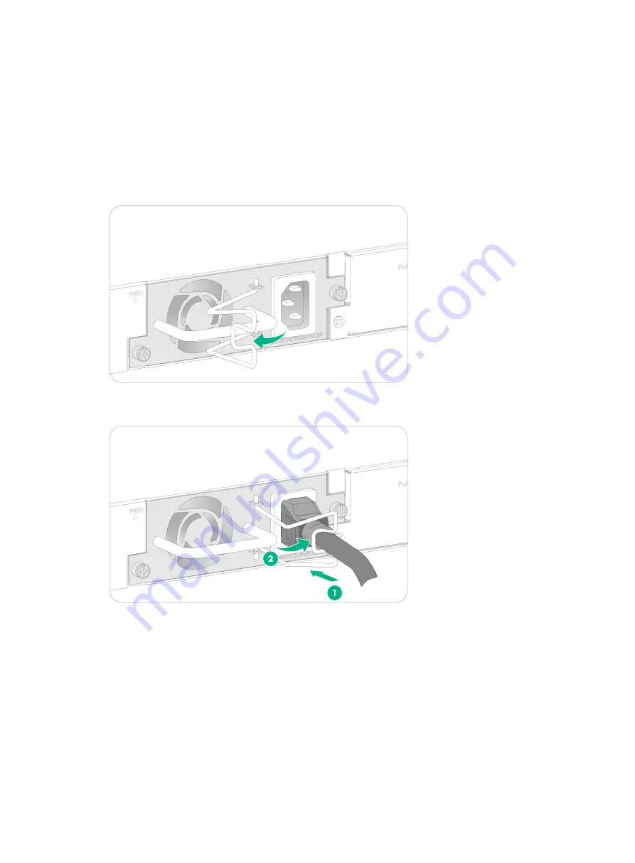
Connect the female connector of the AC power cord supplied with the power supply to the
power receptacle (see callout 1 in
4.
Pull the retainer clip rightwards to secure the connector to the AC-input power receptacle (see
callout 2 in
5.
Connect the other end of the power cord to an AC power source.
Figure2-27 Connecting a power cord (1)
Figure2-28 Connecting a power cord (2)


