background image


A-1 

Appendix A  Lightning Protection of the Switch 

Installation of Lightning Arrester for AC Power (Socket Strip with 
Lightning Protection) 


Lightning arrester will not be shipped with the switch. You should purchase it by yourself if needed. 


If an outdoor AC power cord should be directly led to the switch, please serially connect the lightning 

arrester for AC power (Socket Strip with Lightning Protection) before you plug AC power cord into the 

switch, thus to prevent the possible damage to the switch due to lightning strike. You can use cable clips 

and screws to fasten the lightning arrester for AC power on the cabinet, workbench or the wall of 

equipment room. 

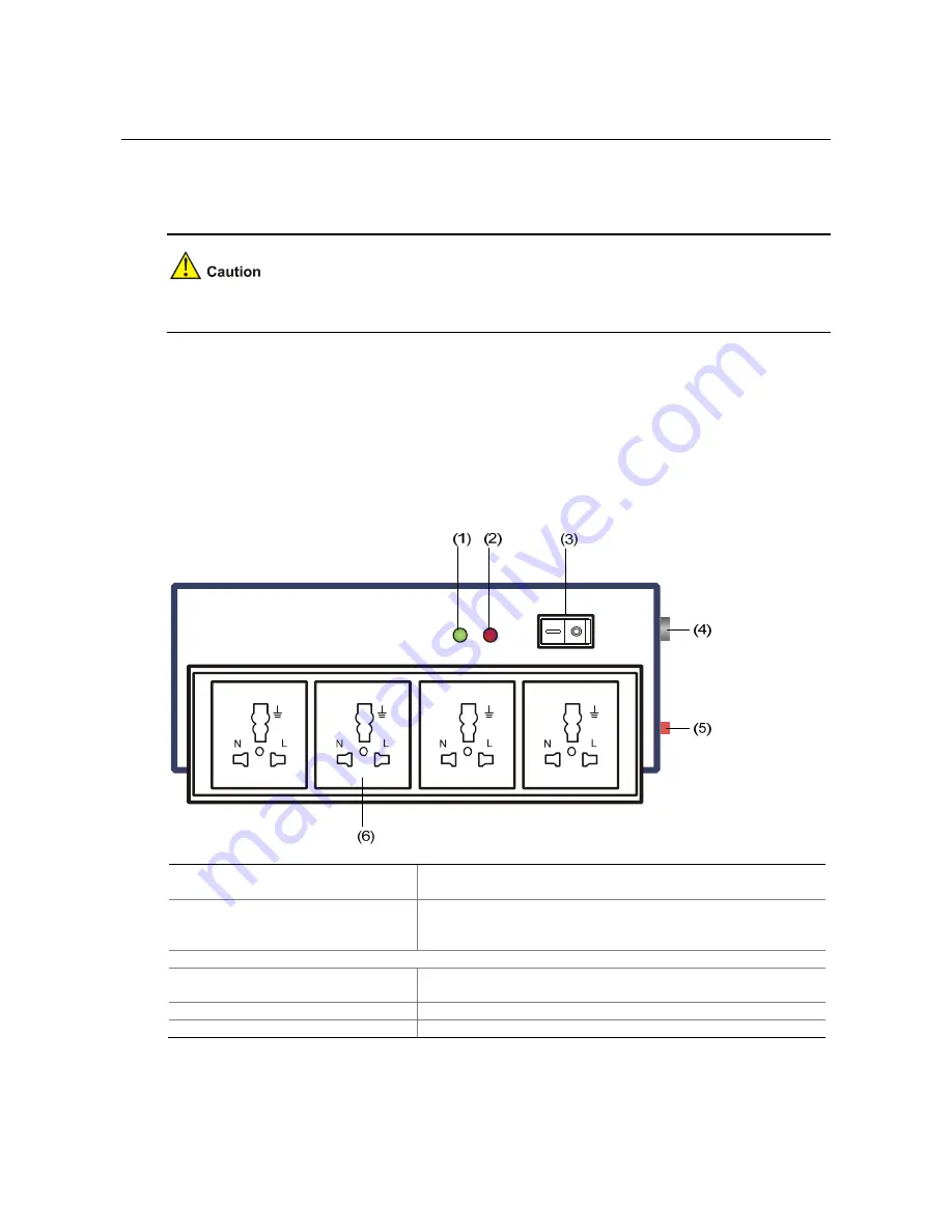
Figure A-1 

Diagram of lightning arrester 


(1) Working LED (green) 

On means the circuit is working normally; off means the 
circuit is damaged.  

(2) Grounding/pole detection LED 
(red) 

On indicates a wrong wire connection (the wire is not 
grounded or the live line and null line are reversely 
connected), and you need to check the power supply line.  

(3) Power switch 

(4) IEC standard socket 

It is used to connect to the power supply in the equipment 
room through a power cord.  

(5) Overload automatic protector 

It can reset automatically.  

(6) Multifunctional socket 

It is used to connect the power module of the device.  


Summary of Contents for S5120-SI Series

Page 1: ...H3C S5120 SI Series Ethernet Switches Installation Manual Hangzhou H3C Technologies Co Ltd http www h3c com Manual Version 6PW102 20090715...

Page 2: ...G Vn G PSPT XGbus N Bus TiGem InnoVision and HUASAN are trademarks of Hangzhou H3C Technologies Co Ltd All other trademarks that may be mentioned in this manual are the property of their respective o...

Page 3: ...ystem files and so on 5 Loading Software Introduces how to load Boot ROM and host software for an S5120 SI series switch 6 Maintenance and Troubleshooting Introduces the problems that might occur duri...

Page 4: ...ct documentation Products Solutions Provides information about products and technologies as well as solutions Technical Support Document Technical Documents Provides several categories of product docu...

Page 5: ...sensing Ethernet port status LED 1 7 1000Base X SFP interface status LED 1 8 2 Installation Preparations 2 1 Safety Precautions 2 1 Installation Site 2 1 Temperature Humidity 2 1 Cleanness 2 1 Electro...

Page 6: ...5 1 Approaches for Loading Application and Configuration Files 5 1 Loading Files Through the Boot ROM Menu 5 1 Introduction to the Boot ROM Menu 5 2 Loading Files Using XMODEM Through Console Port 5 3...

Page 7: ...link direction they are aggregated to large capacity Layer 3 switches or switches at the exchange office through their GE interfaces Table 1 1 shows the models and system specifications of the S5120 S...

Page 8: ...ered in up down and left right order with the first upper left one being Port 1 the first lower left one being Port 2 the second upper left one being Port 3 and so on Rear Panel Figure 1 2 S5120 20P S...

Page 9: ...er 4 Console port 5 1000Base X SFP interface Rear Panel Figure 1 4 S5120 28P SI rear panel 1 AC receptacle 2 Grounding screw Power Supply System AC power input Rated voltage range 100 VAC to 240 VAC 5...

Page 10: ...ce status LED Rear Panel Figure 1 6 S5120 52P SI rear panel 1 2 1 AC receptacle 2 Grounding screw Power Supply System AC power input Rated voltage range 100 VAC to 240 VAC 50 Hz or 60 Hz Input voltage...

Page 11: ...ts varies with the device model see Table 1 1 for details Table 1 3 describes the specifications of the 10 100 1000Base T Ethernet ports Table 1 3 S5120 SI series 10 100 1000Base T Ethernet port speci...

Page 12: ...mode optical fiber 70 km 43 50 miles SFP GE LX SM1310 B IDI TX 1310 RX 1490 SFP GE LX SM1490 B IDI TX 1490 RX 1310 LC 9 125 m single mode optical fiber 10 km 6 21 miles GE SFP transceiver SFP GE T RJ...

Page 13: ...tion status of the switch Table 1 6 Description of the power LED LED Status Description Solid green The switch functions normally Blinking green 1 Hz The system is performing power on self test POST o...

Page 14: ...is not up or does not operate at 10 100 Mbps Solid green The port operates at a rate of 1000 Mbps Fast blinking green Data is transmitted or received at a rate of 1000 Mbps Solid yellow The port opera...

Page 15: ...s for ventilation z The rack or workbench has a good ventilation system z The rack is sturdy enough to support the device and its accessories z The rack or workbench is well earthed To ensure normal o...

Page 16: ...gas limits in the equipment room Gas Maximum concentration mg m3 SO2 0 2 H2S 0 006 NH3 0 05 Cl2 0 01 Electromagnetic Susceptibility The operation of your switch can be affected by external interferen...

Page 17: ...not stare into the optical port because the laser light emitted from the optical fiber may hurt your eyes Installation Tools z Flat blade screwdriver z Phillips screwdriver z ESD preventive wrist str...

Page 18: ...witch into a 19 Inch Rack Using Mounting Brackets The S5120 SI series is shipped with a pair of mounting brackets to fix and support the switch Figure 3 1 shows how to install a S5120 SI series into a...

Page 19: ...used to fix the switch to the mounting bracket Figure 3 3 Four holed mounting bracket 1 Screw hole used to fix the mounting bracket to the rack with an M6 screw 2 Screw hole used to fix the switch to...

Page 20: ...Figure 3 4 and Figure 3 5 S5120 52P SI Front or rear part of the chassis See Figure 3 6 and Figure 3 7 Step1 Place the L2 side of a mounting bracket to the switch and align the mounting holes of the b...

Page 21: ...to the switch For details refer to Attaching the Mounting Brackets to a Switch on page 3 2 Step3 Hold the bottom of the switch and gently place the switch on the rack to a proper location with one per...

Page 22: ...n many cases standard 19 inch cabinets are not available Therefore switches are often placed on clean workbenches To place the switch on a workbench follow these steps Step1 Place the switch with bott...

Page 23: ...securely connected to the earth so that the faradism and leakage electricity can be safely released to the earth enhancing the EMS capability of the switch When a Grounding Strip is Available When a...

Page 24: ...l 5 mm 0 20 in of insulation sheath using a wire stripper and then insert the naked metal part through the insulation covering into the end of the OT terminal Step3 Secure the metal part of the cable...

Page 25: ...no less than 3 5 mm 0 14 in and be zinc coated Weld the yellow green PGND cable to the angel iron or steel tube and treat the joint for corrosion protection Figure 3 11 Ground the switch by burying t...

Page 26: ...power supply Follow these steps to connect an AC power cord Step1 Connect one end of the supplied PGND cable to the grounding screw on the rear panel of the chassis and the other end to the ground as...

Page 27: ...ation around the switch and the rack or workbench is stable z The PGND cable is connected z The selected power module matches that required by the switch z The power cables are properly connected z Al...

Page 28: ...figuration environment setup Connecting the Console Cable Console Cable A console cable is an 8 core shielded cable One end of the cable is a crimped RJ 45 connector which is connected to the console...

Page 29: ...switch z When disconnecting a PC from a powered on switch you are recommended to disconnect the DB 9 connector of the console cable from the PC after disconnecting the RJ 45 connector from the switch...

Page 30: ...nter the HyperTerminal window The Connection Description dialog box appears as shown below Figure 4 3 Connection description of the HyperTerminal Step2 Type the name of the new connection in the Name...

Page 31: ...t Bits per second to 9600 Data bits to 8 Parity to None Stop bits to 1 and Flow control to None Figure 4 5 Set the serial port parameters Step4 Click OK after setting the serial port parameters and th...

Page 32: ...y that z The power cable is properly connected z The power supply voltage meets the requirement of the switch z The console cable is properly connected the terminal or PC used for configuration has be...

Page 33: ...is five seconds The following section describes the setting of the startup mode z If you press Ctrl B within one second the Boot ROM menu is displayed BOOT MENU 1 Download application file to flash 2...

Page 34: ...S5120 CMW520 A1101 bin The main application file is self decompressing Done System is starting User interface aux0 is available Press ENTER to get started The appearance of Press ENTER to get started...

Page 35: ...lays the following information Starting H3C S5120 28P SI BOOTROM Version 107 Creation Date Feb 11 2009 CPU Type ARM926 CPU L1 Cache 32KB CPU Clock Speed 333MHz Memory Type DDR2 SDRAM Memory Size 128MB...

Page 36: ...o get started indicates that the automatic startup of the switch is complete Press Enter The following prompt is displayed H3C You can configure the switch now The H3C series switches provide abundant...

Page 37: ...nterfaces It can be used to upgrade the applications and boot the system Boot ROM program stored together with application programs in the host software package with an extension name of bin used for...

Page 38: ...ng time here is one second If you set the startup mode to normal the waiting time is five seconds For the setting of the startup mode refer to Changing the Boot Mode on page 4 7 z To enter the Boot RO...

Page 39: ...e error packet retransmission mechanism Normally the maximum number of retransmission attempts is ten XMODEM transfer is completed by receiving and sending programs together Receiving program initiate...

Page 40: ...ult Optional Set the baud rate of the serial port on the terminal to be consistent with the default rate of the console port on the switch Restarting the switch to make the updated Boot ROM file effec...

Page 41: ...ters 2 Set FTP protocol parameter Set FTP parameters 3 Set XMODEM protocol parameter Set XMODEM parameters 0 Return to boot menu Return to the Boot ROM menu 3 Configure the switch to download files us...

Page 42: ...ou can skip the step Change the rate of the serial port on the terminal 5 Change the rate of the serial port on the terminal To ensure communication between the terminal and the switch the baud rate o...

Page 43: ...5 7 Figure 5 2 Properties dialog box Figure 5 3 Modify the baud rate Step3 Select Call Call to reestablish the connection...

Page 44: ...tion is displayed Now please start transfer file with XMODEM protocol If you want to exit Press Ctrl X Loading CCCCCCCCCCCCC Press Ctrl X to quit downloading files otherwise proceed as follows 7 Uploa...

Page 45: ...tem asks you whether you want to update the basic Boot ROM section Click Y and then the system displays the following information after the update is completed Updating Basic BootRom Done Updating ext...

Page 46: ...ation file of the switch enter 1 in the Boot ROM menu The system displays the following information 1 Set TFTP protocol parameter 2 Set FTP protocol parameter 3 Set XMODEM protocol parameter 0 Return...

Page 47: ...ed Run the terminal emulation program on the PC connected with the switch s console port Start the switch and enter the Boot ROM menu Then enter the protocol parameter setting menu Enter the protocol...

Page 48: ...te full BootRom 2 Update extended BootRom 3 Update basic BootRom 0 Return to boot menu Enter your choice 0 3 4 Enter the protocol parameter setting menu Enter 1 to update the complete Boot ROM file an...

Page 49: ...te the basic Boot ROM section Click Y Then the system displays the following information after the update is complete Updating Basic BootRom Done Updating extended BootRom Y N Y The system asks you wh...

Page 50: ...ith the attribute the attribute of the existing file becomes none after the new file becomes effective Loading Files Using FTP Through Ethernet Port Introduction to FTP The switch can serve as either...

Page 51: ...downloaded and connect the console port of the switch to a PC as shown in Figure 5 9 Figure 5 9 Load applications using FTP through Ethernet port 2 Run the FTP Server program on the server Run FTP Ser...

Page 52: ...FTP server which should be consistent with that configured on the FTP server z Enter the file name and IP addresses based on the actual condition z If the switch and the server are on the same network...

Page 53: ...Enter your choice 0 3 3 You can enter 2 to load the application file The procedure of loading an application file is similar to that of loading a Boot ROM file The difference lies in that the system d...

Page 54: ...ll update bootrom file on the specified board s Continue Y N y Now updating bootrom please wait Step3 Load the application file and specify the file as the main program file H3C boot loader file updat...

Page 55: ...through TFTP is similar to loading a file through FTP The switch can serve only as a TFTP client that downloads the file from the TFTP server to its flash memory The procedure after download is the s...

Page 56: ...ess software name or path of the TFTP server when using TFTP z Enter an incorrect IP address software name username or password when using FTP If file loading fails when there are neither physical con...

Page 57: ...ults there will not be any screen display at the configuration terminal or the displayed characters will be totally illegible Troubleshooting when there is no terminal display If there is no output in...

Page 58: ...Safety Manual B 1 Regulatory Compliance Information B 1 Regulatory compliance standards B 1 European Directives compliance B 1 USA regulatory compliance B 2 Canada regulatory compliance B 3 Japan regu...

Page 59: ...u can use cable clips and screws to fasten the lightning arrester for AC power on the cabinet workbench or the wall of equipment room Figure A 1 Diagram of lightning arrester 1 Working LED green On me...

Page 60: ...und wire of the arrester is not well grounded or because the live and zero wires are connected in reverse direction You may check that in the following way When the red LED is on use a multimeter to e...

Page 61: ...47 CLASS A ICES 003 CLASS A VCCI 3 CLASS A VCCI 4 CLASS A CISPR 22 CLASS A EN 55022 CLASS A AS NZS CISPR22 CLASS A CISPR 24 EN 55024 EN 61000 3 2 EN 61000 3 3 EN 61000 6 1 ETSI EN 300 386 GB 9254 GB 1...

Page 62: ...directly or indirectly contribute to the equipment incompliance with FCC requirements for Class A digital devices Hangzhou H3C Technologies Co Ltd is not liable for such interference problem and the...

Page 63: ...ISPR 22 for Class A Information Technology Equipment ITE Warning If this equipment is used in a domestic environment radio disturbance may arise When such trouble occurs the user may be required to ta...

Page 64: ...ipment installation and maintenance Lesen Sie bitte alle Arbeitsanweisungen und Sicherheitvorschriften sorgf ltig durch bevor Sie mit dem Arbeiten beginnen Nur durch Beachtung dieser Hinweise l sst si...

Page 65: ...cription Sicherheitssymbole und Beschreibung Safety Symbol Symbole Description Erl uterung Generic alarm symbol To suggest a general safety concern Alarm Hinweis auf ein generelles Sicherheitsproblem...

Page 66: ...ctor or operate the equipment in the absence of a suitably installed ground conductor Contact the appropriate electrical inspection z Betreiben Sie die Ausr stung niemals ohne Erdung Trennen Sie das S...

Page 67: ...Installation der Wechselstromversorgung sind die rtlichen Sicherheitsbestimmungen zu beachten Das Personal muss besonders qualifiziert sein f r das Arbeiten mit Hochspannung und Wechselstrom z AC z Co...

Page 68: ...ung von Leitungen und Verbindungen den rtlichen Anforderungen und Sicherheitsvorschriften entsprechen Arbeiten mit Hochspannung d rfen nur von qualifiziertem Fachpersonal durchgef hrt werden AC Power...

Page 69: ...fen Sie vor dem Anbringen der Zuleitung immer ob das von Ihnen verwendete Kabel den Anforderungen entspricht z For AC power supplied equipment please use 0 75mm2 or 18AWG minimum power supply cord F...

Page 70: ...zard level of this equipment is Class 1 Die von diesem Laser ausgehende Gefahr entspricht der Kategorie 1 1 When performing installation and maintenance operations of optical fibers you should not sta...

Reviews: