background image


19 

a.


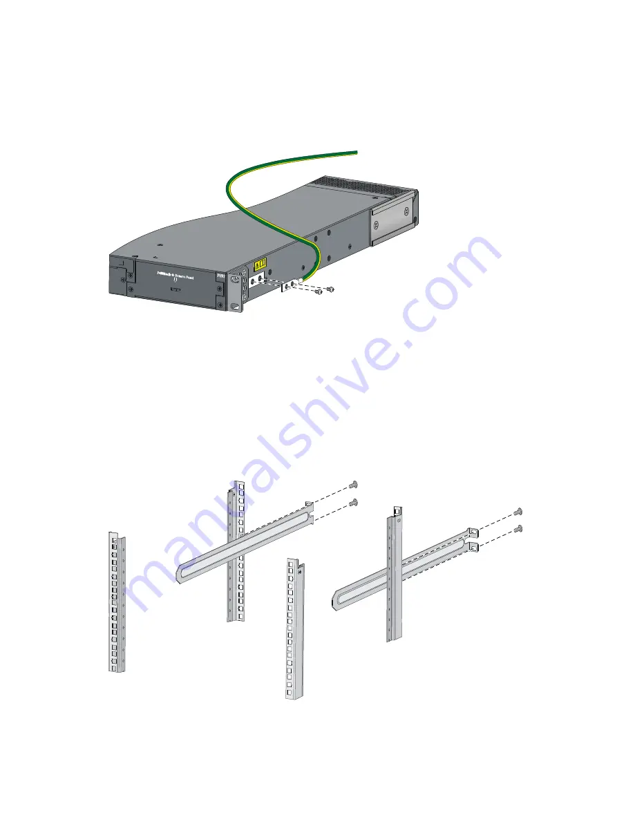
Unpack the grounding cable and grounding screws.  

b.


Align the two-hole grounding lug at one end of the cable with the grounding holes of the 
grounding point, insert the grounding screws into the holes, and tighten the screws with a 
screwdriver to attach the grounding lug to the chassis, as shown in 

Figure 25

Figure 25


Attaching the grounding cable to the chassis 


6.


Attach the slide rails to the rack:  

a.


Identify the rack attachment position for the slide rails. 

b.


Install cage nuts (user-supplied) in the mounting holes in the rack posts. 

c.


Align the screw holes in one slide rail with the cage nuts in the rack post on one side, and use 
M6 screws (user supplied) to attach the slide rail to the rack, as shown in 

Figure 26

d.


Repeat the preceding step to attach the other slide rail to the rack post on the other side.  
Keep the two slide rails at the same height so the slide rails can attach into the chassis rails. 

Figure 26


Installing the slide rails 


7.


Mount the switch in the rack:  

a.


Verify that the front mounting brackets and chassis rails have been securely attached to the 
switch chassis. 


Summary of Contents for S5120-HI Series

Page 1: ...H3C S5120 HI Switch Series Installation Guide Hangzhou H3C Technologies Co Ltd http www h3c com Document version 6W102 20130630...

Page 2: ...gzhou H3C Technologies Co Ltd All other trademarks that may be mentioned in this manual are the property of their respective owners Notice The information in this document is subject to change without...

Page 3: ...Convention Description Boldface Bold text represents commands and keywords that you enter literally as shown Italic Italic text represents arguments that you replace with actual values Square brackets...

Page 4: ...result in data loss data corruption or damage to hardware or software IMPORTANT An alert that calls attention to essential information NOTE An alert that contains additional or supplementary informat...

Page 5: ...ement of expansion interface cards H3C Low End Series Ethernet Switches Pluggable Modules Manual Describes the specifications of pluggable transceiver modules Pluggable SFP SFP XFP Transceiver Modules...

Page 6: ...load Provides the documentation released with the software version Technical support service h3c com http www h3c com Documentation feedback You can e mail your comments about product documentation to...

Page 7: ...mounting by using front mounting brackets 13 Rack mounting by using front and rear mounting brackets 14 Rack mounting by using front mounting brackets and mounting rail assemblies 17 Mounting the swi...

Page 8: ...ntifying physical IRF ports on the member switches 44 Planning the cabling scheme 45 Configuring basic IRF settings 47 Connecting the physical IRF ports 47 Accessing the IRF fabric to verify the confi...

Page 9: ...rt 60 LEDs 60 System status LED 60 Power module status LED 61 Port mode LED 61 Seven segment LED 61 10 100 1000Base T Ethernet port LED 62 SFP port LED 63 SFP port LED 63 Management Ethernet port LEDs...

Page 10: ...nsing Ethernet port 2 10 100 1000Base T Ethernet port LED 3 ACT LED for the management Ethernet port 4 Management Ethernet port 5 LINK LED for the management Ethernet port 6 Console port 7 Seven segme...

Page 11: ...t 8 Port LED mode switching button 9 System status LED SYS 10 SFP port 11 Port mode LED MODE 12 Interface card status LED SLOT 13 SFP port LED 14 Power module 2 status LED PWR2 15 1000Base X SFP port...

Page 12: ...install a fan tray for the switch and make sure the ventilation direction of the fan tray is suitable at the installation site In Figure 3 an LSPM1FAN fan tray is installed Left side panel view Figure...

Page 13: ...P port LED 4 100 1000Base X SFP port 5 Management Ethernet port Management 6 Console port 7 Seven segment LED Unit 8 Port LED mode switching button 9 Port mode LED Mode 10 Power module 1 status LED PW...

Page 14: ...58C HI switches comes with power module slot 1 covered by a filler panel and power module slot 2 empty You can install one or two power modules for the switch as needed In Figure 7 a PSR150 A power m...

Page 15: ...RUs including interface cards power modules and fan trays wear an ESD preventive wrist strap to avoid damaging the units Examining the installation site The S5120 HI switches must be used indoors You...

Page 16: ...s and sulfides to eliminate corrosion and premature aging of components as shown in Table 2 Table 2 Harmful gas limits in the equipment room Gas Maximum concentration mg m3 SO2 0 2 H2S 0 006 NH3 0 05...

Page 17: ...The laser light emitted from the optical fiber may hurt your eyes Installation tools Flat blade screwdriver Phillips screwdriver Long nose pliers Diagonal cutting pliers Marking pen ESD preventive wr...

Page 18: ...N Keep the tamper proof seal on a mounting screw on the chassis cover intact and if you want to open the chassis contact H3C for permission Otherwise H3C shall not be liable for any consequence Figure...

Page 19: ...k mounting procedure 2 Figure 11 Rack mounting procedure 3 Rack mounting restrictions and guidelines Follow the rack mounting restrictions and guidelines in Table 3 depending on the mounting accessori...

Page 20: ...eployment Rack mounting by using front mounting brackets and mounting rail assemblies Only applicable to the S5120 28SC HI and S5120 52SC HI switches Rack requirement Front to back rack depth must be...

Page 21: ...taching to a rack by using an M6 screw 2 Hole for attaching to the switch chassis Figure 13 Rear mounting bracket and load bearing screw 1 Hole for attaching to a rack 2 Load bearing screw Figure 14 R...

Page 22: ...itch for attaching the brackets to the switch chassis b Align the round holes in the wide flange of one front mounting bracket with the screw holes in the port side mounting position see Figure 15 or...

Page 23: ...e power side 5 Connect the one hole lug grounding cable to the rear grounding point see Connecting the rear grounding point to a grounding strip Rack mounting by using front and rear mounting brackets...

Page 24: ...nting bracket with the screw holes in the port side mounting position on one side of the chassis see Figure 20 c Use M4 screws supplied with the switch to attach the mounting bracket to the chassis d...

Page 25: ...ssis with the other hand and pushes the chassis into the rack gently Make sure the load bearing screws closely contact with the upper edges of the rear mounting brackets as shown in Figure 22 b The ot...

Page 26: ...rounding strip Rack mounting by using front mounting brackets and mounting rail assemblies This mounting method is applicable to only the S5120 28SC HI and S5120 52SC HI switches This task requires tw...

Page 27: ...the screw holes in the power side mounting position on one side of the chassis c Use M4 screws supplied with the switch to attach the mounting bracket to the chassis d Align one chassis rail with the...

Page 28: ...or the slide rails b Install cage nuts user supplied in the mounting holes in the rack posts c Align the screw holes in one slide rail with the cage nuts in the rack post on one side and use M6 screws...

Page 29: ...assis rails with the slide rails on the rack posts as shown in Figure 27 Work with another person to slide the chassis rails along the slide rails until the mounting brackets are flush with the rack p...

Page 30: ...nd well grounded 2 Place the switch with bottom up and clean the round holes in the chassis bottom with dry cloth 3 Attach the rubber feet to the four round holes in the chassis bottom 4 Place the swi...

Page 31: ...e at the installation site connect the grounding cable to the grounding strip Connecting the rear grounding point to a grounding strip IMPORTANT Orient the grounding cable as shown in Figure 29 so you...

Page 32: ...g strip and fasten it with the removed hex nut Figure 30 Connecting the grounding cable to a grounding strip 1 Grounding post 2 Grounding strip 3 Grounding cable 4 Hex nut Connecting the side groundin...

Page 33: ...el tube into the earth ground to serve as a grounding conductor The dimensions of the angle iron must be at least 50 50 5 mm 1 97 1 97 0 20 in The steel tube must be zinc coated and its wall thickness...

Page 34: ...uct the grounding system Figure 33 Grounding through the PE wire of the AC power cord 1 Chassis rear panel 2 Three wire AC power cable NOTE To guarantee the grounding effect use the grounding cable pr...

Page 35: ...ssis see callout 2 in Figure 34 If the captive screw cannot be tightly fastened examine the installation of the fan tray Figure 34 Installing an LSPM1FAN fan tray IMPORTANT At the first login to the s...

Page 36: ...CAUTION To prevent damage to the power module or the connectors on the backplane insert the power module gently If you encounter a hard resistance while inserting the power module pull out the power m...

Page 37: ...d 4 Grasp the handle of the power module with one hand and pull it out a little support the bottom with the other hand and pull the power module slowly along the guide rails out of the slot Put away t...

Page 38: ...re 38 Connecting the PSR150 A PSR150 A1 1 Figure 39 Connecting the PSR150 A PSR150 A1 2 Connecting the PSR150 D PSR150 D1 CAUTION Identify the positive and negative marks on the two wires to avoid con...

Page 39: ...ng removing an interface card This section uses the LSPM2SP2P interface card as an example to describe the procedures of installing and removing an interface card For the interface cards available for...

Page 40: ...e card in the slot see callout 2 in Figure 42 Figure 42 Installing an interface card IMPORTANT The LSP5GP8P0 and LSP5GT8P cards can be installed only in SLOT1 of an S5120 34C HI switch and in SLOT1 an...

Page 41: ...nt dust and ensure good ventilation in the switch To remove an interface card 1 Wear an ESD preventive wrist strap and make sure it makes good skin contact and is well grounded 2 Use a Phillips screwd...

Page 42: ...skin contact and is well grounded Then unpack the dedicated SFP cable 2 Hold the connector at one end of the cable with the pull latch on top 3 Orient the connector with the port and insert it into th...

Page 43: ...34 All interface cables are cabled indoors If any cable is routed outdoors verify that the socket strip with lightning protection has been properly connected...

Page 44: ...he console cable Console cable A console cable is an 8 core shielded cable with a crimped RJ 45 connector at one end for connecting to the console port of the switch and a DB 9 female connector at the...

Page 45: ...ers To configure and manage the switch you must run a terminal emulator program on the console terminal The following are the required terminal settings Bits per second 9 600 Data bits 8 Parity None S...

Page 46: ...by the HyperTerminal connection 4 Set Bits per second to 9600 Data bits to 8 Parity to None Stop bits to 1 and Flow control to None and click OK Figure 50 Setting the serial port parameters 5 Select F...

Page 47: ...38 Figure 51 HyperTerminal window 6 On the Settings tab set the emulation to VT100 and click OK Figure 52 Setting terminal emulation in Switch Properties dialog box...

Page 48: ...s on the switch Power on the switch During the startup process you can access Boot ROM menus to perform tasks such as software upgrade and file management The Boot ROM interface and menu options diffe...

Page 49: ...topology and high availability scalability and manageability Table 5 Model matrix for forming an IRF fabric Model S5120 28SC HI S5120 52SC HI S5120 34C HI S5120 58C HI S5120 28SC HI Yes Yes No No S512...

Page 50: ...y and connections Identifying physical IRF ports on the member switches Planning the cabling scheme 2 Install IRF member switches See Installing the switch in a 19 inch rack or Mounting the switch on...

Page 51: ...s Plan the installation site depending on your network solution as follows Place all IRF member switches in one rack for centralized high density access Distribute the IRF member switches in different...

Page 52: ...must bind at least one physical port to it When connecting two neighboring IRF member switches you must connect the physical ports of IRF port 1 on one switch to the physical ports of IRF port 2 on th...

Page 53: ...e expansion interface card can be bound to any IRF port S5120 52SC HI The SFP ports numbered 51 and 52 on the front panel must be bound to different IRF ports For example if you bind SFP port 51 to IR...

Page 54: ...ansceiver modules with optical fibers If the IRF member switches are all in one equipment room choose CX4 SFP cables or twisted pair cables The following subsections describe several H3C recommended I...

Page 55: ...46 Figure 56 Connecting the switches in one rack 1 2 3 4 5 6 7 8 9...

Page 56: ...their member IDs member priorities and IRF port bindings Follow these guidelines when you configure the switches Assign the master switch higher member priority than any other switch Bind physical por...

Page 57: ...Verify that you can manage all member switches as if they were one node 5 Display the running status of the IRF fabric by using the commands in Table 7 Table 7 Displaying and maintaining IRF configura...

Page 58: ...ray without powering off the switch To prevent overheating replace the failed fan tray within 2 minutes You can look at the system status LED and the seven segment LED of an S5120 HI switch to identif...

Page 59: ...iguration terminal displays nothing when the switch is powered on verify the following items The power module is supplying power to the switch The console cable is properly connected The console cable...

Page 60: ...n the rear panel 2 on the rear panel Fan tray slots 1 on the rear panel N A Power module slots 2 on the rear panel 2 on the rear panel AC input voltage Rated voltage 100 VAC to 240 VAC 50 Hz or 60 Hz...

Page 61: ...52 Item S5120 28SC HI S5120 52SC HI S5120 34C HI S5120 58C HI Operating humidity noncondensing 5 to 95 Fire resistance compliance UL60950 1 EN60950 1 IEC60950 1 GB4943...

Page 62: ...Supported Supported Supported LSPM1XP2P Supported Supported Supported Supported LSPM1CX2P Supported Supported Supported Supported LSPM2SP2P Supported Supported Supported Supported LSPM2GP2P Supported...

Page 63: ...1 1 in fans Fan speed 18500 R P M Max airflow 45 CFM Airflow direction Back to front fans blow air from the power module side to the network port side Input voltage 12 V Maximum power consumption 19...

Page 64: ...0 HI Switch Series The transceiver modules available for this switch series are subject to change over time For the most up to date list of transceiver modules consult your H3C sales representative or...

Page 65: ...module Central wavelength Connector Fiber Max transmission distance SFP GE SX MM850 A 850 nm LC 50 125 m multimode 550 m 1804 46 ft 62 5 125 m multimode 275 m 902 23 ft SFP GE LX SM1310 A 1310 nm LC...

Page 66: ...XG LX SM1310 1310 nm LC 9 125 m single mode 10 km 6 21 miles SFP XG LH40 SM1550 1550 nm LC 9 125 m single mode 40 km 24 86 miles SFP cables short haul LSWM1STK N A N A SFP cable 0 65 m 2 13 ft LSWM2ST...

Page 67: ...1550 F1 1550 nm LC 9 125 m single mode 40 km 24 86 miles XFP LH80 SM1550 1550 nm LC 9 125 m single mode 80 km 49 71 miles CX4 cables CX4 cable model Connector Max transmission distance LSPM2STKA 4X In...

Page 68: ...switches have one auto sensing management Ethernet port You can connect this port to a PC or management station for loading and debugging software or remote management Table 10 Management Ethernet por...

Page 69: ...mbo interface see Table 12 These two ports share one transmission channel and cannot work simultaneously When one port in a pair is activated the other port automatically shuts down Table 12 Copper fi...

Page 70: ...t the power module has a problem or no power is being input Off No power module is installed in the power module slot Port mode LED The port mode LED indicates the type of information that the network...

Page 71: ...racter The switch is a candidate switch for a cluster The LED displays a number The member ID of the switch 10 100 1000Base T Ethernet port LED Each 10 100 1000Base T auto sensing Ethernet port has a...

Page 72: ...d port information Table 18 SFP port LED description Port mode LED MODE Mode status Port LED status Description Steady green rate mode Steady green The port is operating at 1000 Mbps The port LED fast...

Page 73: ...on Led mark Status Description LINK Off The management Ethernet port is not connected Steady green The management Ethernet port is operating at 10 100 1000 Mbps ACT Off The management Ethernet port is...

Page 74: ...he interface card The interface cards available for the S5120 HI switches provide one port LED for each port Except for the LSPM2SP2P card see their user manuals for port LED description The LSPM2SP2P...

Page 75: ...an LSPM1FAN fan tray is used cool air flows in through the air vents in the fan tray panel circulates through the chassis and the power modules and exhausts at the network port side When an LSPM1FANB...

Page 76: ...tools 8 Installing the switch in a 19 inch rack 10 Installing removing a fan tray 25 Installing removing a power module 27 Installing removing an interface card 30 Interface cards 54 IRF fabric setup...

Reviews: