background image


Preparing for installation 

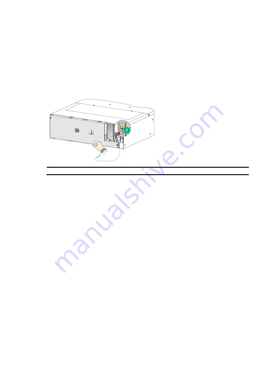
ESD prevention 

To prevent electronic components from electrostatic discharge (ESD) damage, wear an ESD wrist 
strap and make sure it makes good skin contact and is reliably grounded before you touch any 
switch module. 

Figure 1 Attaching an ESD wrist strap 


(1) ESD jack (with an ESD sign) 


Examining the installation site 

The switch must be used indoors. To make sure the switch operates correctly and to prolong its 
service lifetime, the installation site must meet the load-bearing, temperature, humidity, cleanliness, 
EMI, grounding, power supply, ventilation, and space requirements. Reserve a minimum of 1.2 m 
(3.94 ft) of clearance between the switch and walls or other devices. For more information, see 

H3C 

S12500X-AF Switch Series Installation Guide

Installation tools and equipment 

No installation tools and equipment are provided with the switch. Prepare them yourself. 


Summary of Contents for S12502X-AF

Page 1: ...H3C S12502X AF Switch Quick Start Guide New H3C Technologies Co Ltd http www h3c com hk Document version 6PW103 20170630...

Page 2: ...her trademarks that may be mentioned in this manual are the property of their respective owners Notice The information in this document is subject to change without notice Every effort has been made i...

Page 3: ...ling the filler panel 12 Installing cable management brackets 12 Installing and removing fan trays 13 Installing fan trays 13 Removing a fan tray 14 Installing and removing power modules 15 Installing...

Page 4: ...he switch must be used indoors To make sure the switch operates correctly and to prolong its service lifetime the installation site must meet the load bearing temperature humidity cleanliness EMI grou...

Page 5: ...d 30 mm 1 18 in for the fan tray handle at the chassis rear A minimum of 1 1 m 3 61 ft in depth recommended A minimum of 130 mm 5 12 in from the front rack post to the front door A minimum of 950 mm 3...

Page 6: ...he same height on the four rack posts 3 Install cage nuts in the marked square holes on each rack post except for the uppermost marked square holes on the front rack posts See callout 3 in Figure 3 4...

Page 7: ...g brackets Before mounting the chassis in the rack install cage nuts on the front rack posts for attaching the mounting brackets by performing the following steps 1 As shown in Figure 4 determine the...

Page 8: ...chassis To mount the switch in the rack 1 Face the rear of the chassis towards the front of the rack 2 Move the switch by holding the chassis handles 3 Place the switch on the slide rails from the fro...

Page 9: ...connect the grounding cable to the grounding strip 1 Unpack the grounding cable The grounding cable provided with the switch is compliant with the NEBS standards The two hole grounding lug of the gro...

Page 10: ...ing the grounding cable to a grounding strip 1 Grounding sign 2 Use grounding screws to attach the two hole grounding lug to the grounding point 3 Grounding strip 4 Grounding post 5 Ring terminal 6 He...

Page 11: ...st strap Installing and removing MPUs CAUTION If you are not to install an MPU in an MPU slot keep the filler panel in the slot When you install an MPU avoid damaging the connectors on the MPU You can...

Page 12: ...r lever with one hand and the latch with the other pull the MPU part out of the slot See callout 2 in Figure 8 3 Holding the MPU by the front panel with one hand and supporting the bottom with the oth...

Page 13: ...nel is heavy To avoid bodily injury use both hands to install or remove the protective blank panel A protective blank panel is installed over the LPU slots to avoid switch damage during transportation...

Page 14: ...outward to the outmost when most of the LPU is inserted into the slot 4 Push the LPU until the brakes on its ejector levers touch the slot edges tightly 5 As shown by callout 3 in Figure 10 continue...

Page 15: ...the spring tab when you remove a cable management bracket The cable management brackets are installed on the two sides of the LPU slots As a best practice install cable management brackets after you...

Page 16: ...utomatically increases the fan rotation speed and makes louder noise Take protection measures such as wearing an earmuff or earplug In addition make good preparation before the hot swapping to minimiz...

Page 17: ...in Figure 14 loosen the captive screws on the fan tray 2 Squeezing the captive screw at the air vents side with one hand and holding the fan tray handle pull the fan tray outward until it is disengage...

Page 18: ...2 Correctly orient the power module If you install the power module in a left power module slot make sure the latch is above the handle If you install the power module in a right power module slot mak...

Page 19: ...To remove a power module 1 Hold the handle on the power module with one hand and pull downward the latch See callout 1 in Figure 16 2 Pull the power module part out of the slot Holding the bottom of t...

Page 20: ...e the power cord to the handle of the power module 3 Plug the other end of the power cord into an AC power receptacle and turn on the circuit breaker Figure 17 Using a removable cable tie to secure th...

Page 21: ...e positive terminal on the power module 3 Fasten the M5 screws to secure the wires and then install the plastic cover 4 Connect the other end of the power cord to the power source Turn on the circuit...

Page 22: ...a rack 1 Install cage nuts on the rack posts 2 Use screws to attach the DC input terminal block to the rack Figure 19 Attaching a DC input terminal block to a rack To connect power wires to a DC inpu...

Page 23: ...o not remove the dust plug from the SFP SFP QSFP QSFP28 module if you are not to connect an optical fiber to the module Before you install an SFP SFP QSFP QSFP28 module remove the optical fiber if any...

Page 24: ...iber diameter The cables are hot swappable Use SFP cables to connect SFP ports QSFP cables to connect QSFP ports QSFP28 cables to connect QSFP28 ports and QSFP to SFP cables to connect QSFP and SFP po...

Page 25: ...onsideration of the layout of the equipment room including the locations of the power distribution cabinet AC power receptacles and lightning protection box Place all re connecting facilities such as...

Page 26: ...DB 9 female connector of the console cable to the serial port of the PC 2 Plug the RJ 45 connector of the console cable to the console port of the switch Figure 22 Connecting a terminal to the console...

Page 27: ...otWare is self decompressing Done BootWare Version 2 03 Compiled Date Aug 10 2016 CPU Type XLP208 CPU Clock Speed 1000MHz Memory Type DDR3 SDRAM Memory Size 8192MB Memory Speed 666MHz BootWare Size 15...

Page 28: ...appears you can configure the switch After the switch finishes startup verify the following items The cooling system is working and you can hear fan rotating noise and feel air being blown out The LED...

Page 29: ...from the H3C website at www h3c com hk 1 Go to http www h3c com hk Technical_Documents 2 Choose the desired product category and model Copyright 2016 2017 New H3C Technologies Co Ltd For more informa...

Reviews: