the small signal MATLAB model. This simulation is more realistic than the MATLAB
model.
For slow systems ( system with large inductance, > .01 Henry) you will need to slow the
signal generator frequency in order to observe the steady state response of the system. Note
that both these simulations give you a starting point for the tuning values and you may still
need to adjust these on the actual system.
Power Supply
Power must be applied to these pins with the correct polarity, otherwise the amplifier may
be damaged.
Only isolated-secondary type power supplies should be used. The power
supply should be a floating type supply, and not referenced to ground on
the secondary.
The amplifier employs an under-voltage lockout system to disable the amplifier in the event
that the supply voltage falls below 27 volts. This feature may be disabled by removing the
jumper J2 (RESET EN) from the 1-2 position and placing it in the 2-3 position. Note that
this action will disable the power-up / power-down circuitry as well, and may result in
surges at the output terminals of the amplifier. Power supply voltages below 27 volts may
affect the performance of the amplifier.
Reversing the power supply connection may result in permanent damage
to the amplifier.
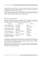
Pin Number
Function
1
POWER +
(27 – 60 Volts)
2
POWER -
Table 5. Power supply connection.
24
Power Amplifier Module User's Guide


