background image

 |


21

Temperature Switch TSM 125

WARNINGS AND SAFETY INSTRUCTIONS

Please read this manual carefully.

 It contains important information for the safe 

operation and use of this device. The law requires that we give you important 
information for your safety and that we point out how to avoid damage to 
persons, the device and the connected devices. No liabilities will be taken 
for damages or claims resulting out of not reading and/or not following the 
user guide and/or any form of modification on or in the product. Under these 
circumstances, no warranty services will be given. Liability will not be taken for 
consequential damages. These instructions are part of the device and should 
therefore be stored carefully. In order to avoid malfunction, damage and health 
problems, please follow the safety instructions carefully:
– Repairs may only be carried out by an expert.
–  Dispose of the packaging material and keep it out of reach of children. There 

is a danger of suffocation

–  Electrical devices do not belong in the hands of children. Store the device in 

a safe place. 


DANGER! 

The device may only be opened by a qualified electrician! 

An open device has accessible live components. The mains plug must 
be pulled before the device is opened.

TECHNICAL DATA 

– Operating Voltage: 10 – 15 V DC
– Power current: 60 mA
– Switching power: 5 A 250 V AC oder 5 A 30 V DC
– Wattage: max. 1000 W
– Measuring range: –55°C to +125,0°C
– Accuracy:  (–55°C to –10°C):   +/–2°C
     

(–10°C to +85°C):   +/–0,5°C


(+85°C to +125°C):  +/–2°C

– Resolution: 0,1°C
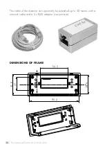
– Dimensions (L x B x H): 101 x 47 x 35 mm
– Cutout for front frame: 97 x 43 mm 

Summary of Contents for TSM 125

Page 1: ...www h tronic de TEMPERATURSCHALTER TSM 125 Art Nr 1 11 44 30...

Page 2: ...Fehlermeldungen 15 10 Pflege Wartungshinweise 16 11 Garantie Gew hrleistung 16 12 Entsorgung 17 13 Thermof hler 18 ENGLISH MANUAL page 20 1 Designated use 22 2 General safety instructions 22 3 Safety...

Page 3: ...f r Digital thermometer dienen D MERKMALE Temperaturf hler mit Befestigungslasche Min Max Anzeige Schalttemperatur von 55 125 C frei einstellbar in 0 1 C Schritten Hysterese frei einstellbar Fernmess...

Page 4: ...folgende Sicherheitshinweise Eine Reparatur des Ger tes darf nur vom Fachmann durchgef hrt werden Entsorgen Sie nicht ben tigtes Verpackungsmaterial oder bewahren Sie dieses an einem f r Kinder unzug...

Page 5: ...t spielen Schlie en Sie das Ger t nur an eine vorschriftsm ig installierte Steckdose an Die Spannung muss mit der Angabe auf dem Typschild des Ger tes ber einstimmen Klemmen Sie das Netzkabel nicht e...

Page 6: ...ig hervorgeht welche elektrischen Kennwerte f r ein Bauteil oder eine Baugruppe gelten wie eine externe Beschaltung durch zuf hren ist oder welche externen Bauteile oder Zusatzger te an ge schlossen w...

Page 7: ...muss ein Schutz gegen Ber hrung gew hrleistet sein bzw darf das Ger t nur in einem ber h rungsgesch tzten Geh use betrieben werden In diesem Fall darf das Ger t nur durch eine fachkundige Person oder...

Page 8: ...n bzw best tigen 6 PROGRAMMIERMODI 6 1 F R GER TE MIT FIRMWARE V1 00 Ger te bis Mitte 2016 Wenn die Taste SET gedr ckt wird geht das Ger t in den Einstellungsmodus Dabei werden die folgenden Men Punkt...

Page 9: ...igt Der Wert kann mit den Tasten pq gel scht werden Wenn die Einstellung beendet ist wird dies mit der Taste SET best tigt Danach kehrt das Ger t in den Anzeige Mo dus zur ck Wenn zu diesem Zeitpunkt...

Page 10: ...nstellungsbereich 55 0 C 125 0 C MEN PUNKT N2 Off 25 1 In diesem Menu Punkt wird die Ausschalttemperatur in 0 1 Grad Schritten einge stellt Der Wert kann mit den Tasten pq ge ndert werden Wenn die Ein...

Page 11: ...angezeigt Der Wert kann mit den Tasten pq gel scht werden Wenn die Einstellung beendet ist wird dies mit der Taste SET best tigt Das Ger t geht zum n chstem Menu Punkt MEN PUNKT N5 Lo 5 4 In diesem M...

Page 12: ...S ist Beispiel Programmieren Sie eine Einschaltschwelle von 23 C E23 und eine Ausschaltschwelle von 25 C A25 Das Ger t erkennt daran dass es sich um einen Heizvorgang handelt Ausschaltschwelle h her a...

Page 13: ...tr gt 23 C zieht das Relais nicht an Erst wenn die Temperatur unter 20 C f llt schaltet das Relais ein und f llt bei Erreichen von 25 C wieder ab Umgekehrt trifft dies auch im Bereich K hlen zu 8 SERI...

Page 14: ...0x0A 2 ASCII 1 5 LF CR Hex 0x20 0x20 0x31 0x2E 0x35 0x0D 0x0A 3 ASCII 11 2 LF CR Hex 0x2D 0x31 0x31 0x2E 0x32 0x0D 0x0A 4 ASCII Err 1 LF CR Hex 0x45 0x72 0x72 0x2E 0x31 0x0D 0x0A 5 ASCII Err 3 LF CR...

Page 15: ...bit 9 FEHLERMELDUNGEN Das Ger t kann folgenden Fehler anzeigen Fehler N1 Err1 HINWEIS Bei Auftreten eines Fehlers schaltet das Ger t zwangsl ufig das Relais aus Es wurde ein Kurzschluss im Thermof hle...

Page 16: ...e Liefe rung eines Ersatzproduktes Ausgetauschte Ger te oder Teile gehen in das Ei gentum des H ndlers Herstellers ber Der K ufer hat festgestellte M ngel dem H ndler unverz glich mitzuteilen Der Nach...

Page 17: ...ng oder Stromart Bei Fehlbedienung oder Sch den durch fahrl ssige Behandlung Bei Defekten die durch berbr ckte Sicherungen oder durch Einsatz falscher Sicherungen entstehen In all diesen F llen erfolg...

Page 18: ...optional erh ltliche Kunststoff F hler erlaubt auch Temperaturmessungen in Fl ssigkeiten Es darf sich hier jedoch nicht um aggressive chemische oder reaktive Fl ssigkeiten handeln Der Sensor ist au er...

Page 19: ...19 Temperaturschalter TSM125 ABMESSUNG EINBAURAHMEN ANSCHLUSSBEISPIEL 12V DC 10 15V z B 230 V AC Verbraucher...

Page 20: ...TEMPERATURE SWITCH TSM 125 Art No 1 11 44 30 GB FEATURES Temperature sensor with fastening strap Minimum Maximum display Selectable switching temperature between 55 C and 125 C in 0 1 C increments Sel...

Page 21: ...e and should therefore be stored carefully In order to avoid malfunction damage and health problems please follow the safety instructions carefully Repairs may only be carried out by an expert Dispose...

Page 22: ...from sharp edges moisture heat or oil Do not connect the device if the power cord is damaged In order to avoid a hazard or electrocution a damaged power cord must be replaced immediately by our servic...

Page 23: ...from improper use or incorrect installation of the device MALFUNCTION Only use the device if it is functioning without disturbance If there is any malfunction switch off the device immediately and con...

Page 24: ...ional associations must be followed In schools training centers clubs and workshops the operation of modules must be monitored by responsible trained personnel If the device needs to be repaired only...

Page 25: ...d device is to be switched off e g 21 C Press button OK The value then can now be changed with the buttons pq The selection is confirmed by pressing the button SET and the device will move to the next...

Page 26: ...possible NOTE Every menu item consists of two displays that appear after each other the first display shows the name of the menu the second display will indicate its value When pressing SET the devic...

Page 27: ...you the turn on delay of the relay The value can be selected by pressing pq The selection is confirmed by pressing SET and the display will switch to the next step This setting is useful if ON and OF...

Page 28: ...ions depending on pro gramming FUNCTION THERMOMETER This function is activated if the programmed switching ON temperature is identical to the switching OFF temperature The three LEDs and the relay are...

Page 29: ...o T AUS For example a switching ON temperature of 25 C is programmed and a swit ching OFF temperature of 22 The device recognizes that this is a cooling mode and shows this by switching on the K hlen...

Page 30: ...of 7 ASCII bytes The first 5 bytes are information and the last two bytes are CR LF The first five bytes will either contain temperature data or an error indication Examples 1 ASCII 121 1 LF CR Hex 0x...

Page 31: ...following error messages Error N1 Err1 Error N3 Err3 NOTE if an error message is displayed the relay is automatically switched off Pin 1 GND Pin 2 RX input Pin 3 TX output Pin 4 5V output Error N2 Err...

Page 32: ...g any defects immediately together with the purchasing invoice The dealer manufacturer cannot be made liable for defects or malfunctions that occur due to incorrect handling incorrect mounting incorre...

Page 33: ...g of electrical and electronic equipment waste This device and or components within the device must be recycled For more information concerning disposal sites please con tact your local authority or w...

Page 34: ...34 Temperature Sensor and connections The cable of the detector can optionally be extended up to 50 meters with a network cable and a 2 x RJ45 adapter see pictures DIMENSIONS OF FRAME...

Page 35: ...is according to the technical status at the time of printing and is a constituent part of the device We reserve the right to make technical changes to the construction equipment and design Copyright...

Page 36: ...z B Fotokopie Mikroverfilmung oder die Erfassung in EDV Anlagen bed rfen der schriftlichen Genehmigung des Herausgebers Nachdruck auch auszugsweise verboten Diese Bedienungsanleitung entspricht dem t...

Reviews: