background image

TX AND ORX STABILISATION

DEVICE SETUP 

Note: If you wish to set up Expo/Dual rates on the elevator and aileron 

channels to meet your flying style, you must set them only under the 

Intermediate and Expert flight mode.

SWITCH ON THE TX

Place your F-1

8

 50mm EDF on level ground. Plug in your battery flight pack and let 

it sit still, during this time the plane is in auto self-calibration mode. The LED light on 

the stabilization device will keep flashing rapidly for 3-6 secs, then the light will 

remain solid. In the mean time the aileron, 

and 

elevator control surfaces will move 

up/ down

and left/right 3 times to indicate the self-calibration is successful. 

When the self calibration has been carried out the stabilization system is still 

not in ready mode.  Now check to see if all the control surfaces are in a 

neutral position. If not, please adjust the push-rod clevises to ensure all the 

control surfaces are neutral before flight, then cycle the battery power to 

store this setup. 

After all these setup procedure have been completed, plug in the battery once 

again and wait until all the control surfaces move up/down and left/right 3 

times to confirm the self- calibration before flight. 

At this point the gyro is not in ready mode until you give the throttle a short 

blip 10-15% in order to switch on the stabilization system. Check that the gyro 

responds accordingly to the plane when being tilted up/down in pitch, 

left/right in roll. 

10

Summary of Contents for F-18 50MM EDF 4S

Page 1: ...INSTRUCTION MANUAL H KING F 18 50MM EDF 4S WITH ORX FLIGHT STABILIZER ...

Page 2: ...esult in a momentary loss of control so it is always recommended that this product be used in a suitable open outdoors space This is a radio controlled flying model and as such must always be flown with caution this is NOT a toy The H King brief was to design a model for low hours to intermediate pilots Always exercise great caution when using the recommended battery to power this product For full...

Page 3: ...t w battery 4S Li Po 1300 mAh 500g 10g Power 50mm EDF 4S high power brushless motor Radio Radio 6ch and up with electronic mixing capability computer radio Recommended Battery 1000 1300 mAh 4S Li Po 30 60C Recommended ESC 30A with BEC Servo 4 x 9g 2 ...

Page 4: ...CONTENTS 1 Fuselage 2 Canopy 3 Main wing set 4 Vertical fin 5 Horizontal stabilizer 6 Nose cone 7 Carbon fiber wing joiner 8 Pushrods 9 Double sided tape 1 3 ...

Page 5: ...and connect the wing servo lead Then gently push the wing against the fuselage until it hits the magnet on the wing saddle The servo lead should also be tucked nicely inside the groove in between the wing and the fuselage The built in magnet wing locking system on the wing saddle will hold the wing securely 3 Repeat Step 2 for the left wing 4 ...

Page 6: ... steps for the right hand side horizontal stabilizer 3 View the model from the front ensure the left and right horizontal stabilizer are installed correctly check this frequently as the glue dries VERTICAL FIN Apply a thin layer of foam safe glue to one of the vertical fins and install it onto the fuselage as shown Repeat this process for the other fin check the alignment frequently as the glue dr...

Page 7: ...NOSE CONE YOUR F 18 BUILD IS COMPLETE 6 Use a foam safe glue to attach the nose cone ...

Page 8: ... C of G is 48 53 mm from the wings leading edge For first flights we recommend you use the forward measurement Once you get used to the model you can then move it back do not though exceed the most rearward measurement 7 ...

Page 9: ... assigned for flight mode selection PWM input Ch 1 Aileron Ch 2 Elevator Ch 3 Throttle and Ch 5 Flight mode a 3 way toggle switch should be assigned for flight mode selection PPM input Plug the flight mode SBUS PPM channel input plug into your receiver which supports PPM out Here is the Ch assignment and shown as follow Ch 1 Aileron Ch 2 Elevator and Ch 3 Throttle Ch 5 a 3 way toggle switch should...

Page 10: ...m at 100 and expo at 0 There are two sets of pushrods which come with the kit The shorter ones are used for ailerons and the longer ones are used for elevators Install the supplied longer pushrod to the right hand side elevator servo horn and use the third hole from the top as shown Then repeat the above steps for the elevator servo on the left hand side If you are happy with the above setup you m...

Page 11: ... the self calibration is successful When the self calibration has been carried out the stabilization system is still not in ready mode Now check to see if all the control surfaces are in a neutral position If not please adjust the push rod clevises to ensure all the control surfaces are neutral before flight then cycle the battery power to store this setup After all these setup procedure have been...

Page 12: ...ill move less Set the stabilization system into beginners mode then check that it is working correctly by doing the following test Roll the aircraft to the right the left aileron should go up and the right down Roll the aircraft to the left and the right aileron should go up and the left down Move the nose down and the elevator should go up move the nose up and the elevator should go down If all w...

Page 13: ...ck to the left the left aileron should go up Roll Right Move the aileron stick to the right the right aileron should go up Pitch Up Move the elevator stick down the elevator should go up Pitch Down Move the elevator stick up the elevator should go down RC CONTROL ...

Page 14: ... is in the middle position Gyro On perform the same actions as above the servos will still move but to a lesser degree In this mode the gyro will still be assisting your flying and helping smooth things out but it does not limit the roll and pitch angles nor will it self right as quickly In this mode you will be able to perform simple aerobatics when you are ready 4 Now put the switch into the Gyr...

Page 15: ...ll Limited adio range 1 Charge replace batteries Model moves backwards Charge the batteries Install a charged battery Check connection between the ESC and motor Replace motor Consult adio manual and go through bind procedure again Hold model and move throttle to full position then back down to idle 1 The servo lead is connected to Rx incorrectly 2 The servo is damaged Make sure the servo leads are...

Page 16: ...s 1000 mAh 4S 70C Lipo Pack w XT60 SKU 9210000262 0 Turnigy Graphene Panther 1000 mAh 4S 75C Battery Pack SKU 9067000360 0 Turnigy nano tech 1000 mAh 4S 45 90C Lipo Pack SKU N1000 4S 45 Turnigy 1300 mAh 4S 60C Lipo Pack w XT60 SKU 9067000520 0 15 ...

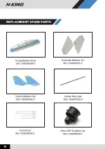
Page 17: ...REPLACEMENT SPARE PARTS 16 ...

Page 18: ...UK REP EC REP APEX CE SPECIALISTS LIMITED 89 Princess Street Manchester M1 4HT UK APEX CE SPECIALISTS LIMITED Unit 3D North Point House North Point Business Park New Mallow Road Cork T23 AT2P Ireland ...

Reviews: