GDM-397/GDM-461 User Manual
61
Warning
To avoid electrical shock or arc blast, or personal injury or damage to the Meter,
use specified fuses ONLY in accordance with the following procedure.
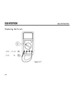
To test the fuse: (See figure 13)
If the Meter does not respond when measuring current, inspect to see that the fuses
aren’t broken.
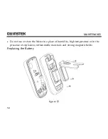
To replace the Meter’s fuse: (See figure 12)
1.
Turn the Meter power off and remove all the connections from the terminals.
2.
Remove the screw from the tilt stand and the battery compartment and
separate the battery compartment and the tilt stand from the case bottom.
3.
Remove the two screws from the case bottom, and the separate the case top
from the case bottom.
4.
Remove the fuse by gently prying one end loose, then take out the fuse from its
bracket.
5.
ONLY install replacement fuses of an identical type and specification as shown
below and make sure the fuse is fixed firmly in the bracket.
uA/mA range:
F1, 1A H 240V,
φ
6x25mm (CE)
Summary of Contents for GDM-397
Page 22: ...MEASUREMENT OPERATION 20 C Resistance Measurement see figure 4 mAuA COM V Hz figure 4...
Page 25: ...GDM 397 GDM 461 User Manual 23 D Testing for Continuity see figure 5 figure 5...
Page 27: ...GDM 397 GDM 461 User Manual 25 E Testing Diodes see figure 6 figure 6...
Page 30: ...MEASUREMENT OPERATION 28 F Capacitance Measurement see figure 7 mAuA V Hz figure 7...
Page 35: ...GDM 397 GDM 461 User Manual 33 H Temperature Measurement GDM 397 only see figure 9 figure 9...


