MEASUREMENT OPERATION
22
Note
The test leads can add 0.2
Ω
to 0.5
Ω
of error to the resistance measurement. To
obtain precise readings for low-resistance measurements, short the leads
beforehand to obtain the resistance of the test leads and use the relative
measurement function button,
REL
, to automatically subtract the resistance of
the test leads from the measured value.
If the
Ω
reading with shorted test leads is not ≤0.5
Ω
, check to see that the test
leads are properly connected and are not loose.
For high-resistance measurements (>1M
Ω
), it is normal to take several seconds
to obtain a stable reading. To obtain a stable reading, use test leads that are as
short as possible or use the included multi-purpose socket to carry out the
measurement.
The LCD displays
OL
to indicate an open-circuit or that the resistor value is
higher than the selected range of the Meter.
When resistance measurement has been completed, disconnect the connection
between the testing leads and the circuit under test, and remove the testing leads
away from the input terminals of the Meter.
Summary of Contents for GDM-397
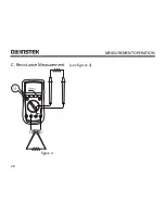
Page 22: ...MEASUREMENT OPERATION 20 C Resistance Measurement see figure 4 mAuA COM V Hz figure 4...
Page 25: ...GDM 397 GDM 461 User Manual 23 D Testing for Continuity see figure 5 figure 5...
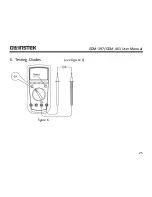
Page 27: ...GDM 397 GDM 461 User Manual 25 E Testing Diodes see figure 6 figure 6...
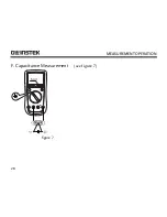
Page 30: ...MEASUREMENT OPERATION 28 F Capacitance Measurement see figure 7 mAuA V Hz figure 7...
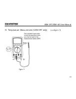
Page 35: ...GDM 397 GDM 461 User Manual 33 H Temperature Measurement GDM 397 only see figure 9 figure 9...


