background image

Mobile NVRs M1184 / M1284 Quick Start Guide

25

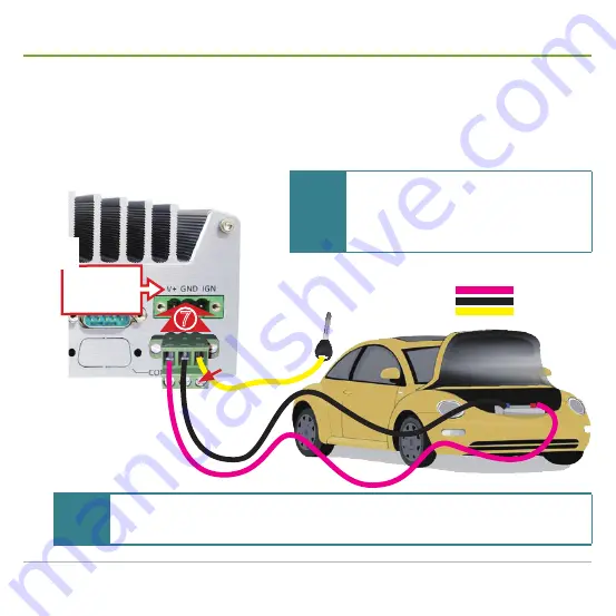
Wire DC-in Power Source

polarities between the wires and the terminal block plugs must be positive to positive and negative to 

negative.

6.  Use a slotted screwdriver to tighten the captive screws.


7. 

Plug the terminal block onto the DC-in power jack on the mobile NVR. And fix the connection by 

fastening two screw on the terminal block.

See the symbols 

printed above 

the DC-in power 

jack.

V+

GND

IGN

V+ GND IGN

captive 

screw

Note

If the mobile NVR is used on a train, it is recommended that you use an additional EN50155-

compliant single-output DC-to-DC converter or let the mobile NVR tap from UPS (uninterruptible 

power supply).

Note

The mobile NVR accepts only 8~35 VDC for 

DC input. Make sure your power source is 

compliant with this voltage before you tap the 

power. Supplying power over 35V will damage the 

system.

Summary of Contents for M1184

Page 1: ...GVD Mobile NVRs M1184 M1284 Quick Start Guide...

Page 2: ......

Page 3: ...lus GPS Module Optional 16 Install a SIM Card 19 Install Internal SATA HDDs SSDs 20 Install Outside accessible SATA HDD SSD 22 Mount the Mobile NVR 23 Wire DC in Power Source 24 Manage Ignition Power...

Page 4: ...and if not installed and used in accordance with the instruction manual may cause harmful interference to radio communications Operation of this equipment in a residential area is likely to cause harm...

Page 5: ...t of the GVD certified hard disk drives at the link below http www gvdigital com gvdweb html document Support_Lists Certified 20HDD 20List pdf NOTE GVD does not guarantee the system performance if a H...

Page 6: ...Mobile NVRs M1184 M1284 Quick Start Guide iv...

Page 7: ...ou opt for a GPS plus 3G or 4G module to go inside the mobile NVR the control center can instantly locate the vehicle that carries the mobile NVR on the map Also on option is a G sensor to measure the...

Page 8: ...N WPER 172GN 802 11b g n USB Half Mini Card 802 11b g n ISM Band 2 400 2 4835GHz Antenna 2 x U FL connectors diversity antenna 1T1R 1 x External Antenna RP SMA male body female inner contact A few scr...

Page 9: ...ernal Antenna Length 300cm RP SMA male body male inner contact A few screws to fix the module Stainless steel round philips screws North America Latin America Sierra Wireless AirPrime MC7354 w 15cm in...

Page 10: ...sockets inside the mobile NVR See also Install Internal SATA HDDs SSDs on page 20 Reset button Restarts the system without turning off the power To prevent false trigger this button is recessed in th...

Page 11: ...rd mouse Implemented with industrial grade ITE8783 Super IO chip 40 to 85 C Ethernet LAN port One Gigabit Ethernet port with Intel 82579LM controller with status LEDs Supports Intel AMT Active Managem...

Page 12: ...8 IGN 9 WDT Output Status LED for watchdog timer Blinks when the watchdog timer is started 10 WDT Make sure the polarity is correct when connecting the external status LED to the status LED outputs U...

Page 13: ...on control Pinout Pin Def Description 1 V Positive polarity of DC power input from 8V 35V 2 GND Gound of DC in power 3 IGN Ignition signal input e g the ACC power of vehicles 1 Make sure the voltage o...

Page 14: ...ng up to 25 5 W 80W total budget When only one of the four ports is occupied a maximal 1000 MB s bandwidth is achievable When all four ports are connected all devices share 1000 MB s bandwidth i e 250...

Page 15: ...on control Pinout Pin Def Description 1 V Positive polarity of DC power input from 8V 35V 2 GND Gound of DC in power 3 IGN Ignition signal input e g the ACC power of vehicles 1 Make sure the voltage o...

Page 16: ...RTS 8 CTS 422 TXD 485 TXD RXD 9 RI 5 1 6 9 M12 PoE LAN ports 8 Power over Ethernet LAN ports with M12 connectors that feature the following M12 A codig 4A 4P female connector Delivering up to 25 5 W...

Page 17: ...tate the work Follow the guide below to open the mobile NVR and access the motherboard 1 Place the mobile NVR on a flat and soft surface Find the SATA storage tray knobs perching on one side of the mo...

Page 18: ...nal block before you can completely part the rear panel from the mobile NVR Disconnect the DC in terminal block The inside of the mobile NVR then comes to view 3 Loosen and remove the four M3 F head s...

Page 19: ...at the socket without a SIM card holder The connector has a break among the contact pins Connector s break Mini Card socket socket for a WiFi module or some other wireless module socket for a 4G modul...

Page 20: ...onnector exactly as illustrated below Connect the antenna wire to the the U FL connector exactly as shown 9 Pull the other end of the antenna wire a SMA connector jack through the antenna hole Be sure...

Page 21: ...get stuck Arrange the antenna wire in this indentation 13 Restore the bottom panel left panel and right panel to the mobile NVR 14 Put on the external antenna for WiFi Note If the mobile NVR has more...

Page 22: ...te the 3G or 4G plus GPS module should be installed at the socket that goes with a SIM card holder The connector has a break among the contact pins Connector s break Mini Card socket socket for a WiFi...

Page 23: ...or 4G and GPS antennas be pulled through the antenna holes at the rear panel WiFi WiFi 3G 4G GPS GPS3G 4G 3G 4G plus GPS antennas to be pulled through the antenna holes at the rear panel 8 Pull the ot...

Page 24: ...commanded that you lay out the antenna wires and the external antennas as illustrated below WiFi WiFi 3G 4G GPS GPS3G 4G 11 Pull the wire along the indentation between the motherboard and the enclosur...

Page 25: ...d access the motherboard as described in Access Motherboard on page 11 The top side of the motherboard then comes to view 2 Find the SIM card holder on the motherboard 5 Slide a SIM card along the hin...

Page 26: ...e outside accessible ones see Install Outside accessible SATA HDD SSD on page 22 1 Place the mobile NVR on a flat and soft surface Find the SATA storage tray knobs perching on one side of the mobile N...

Page 27: ...on a flat surface with the top cover up Face the SATA connectors SATA connectors for internal SATA HDDs SSDs 4 Have a SATA HDD or SSD of 2 5 Plug the HDD or SSD to one of the SATA connectors inside P...

Page 28: ...ternal SATA HDDs SSDs on page 20 1 Place the mobile NVR on a flat surface Find the SATA storage tray knobs perching on one side of the mobile NVR Select either one to install your SATA HDD SSD First l...

Page 29: ...l mount kit to the mobile NVR 1 Have the wall mount kit from the accessories of the mobile NVR The kit includes 4 x M3 P Head screws and 2 x metal brackets 2 Place the mobile NVR upside down on a flat...

Page 30: ...ly wired 1 Identify the positive and negative terminals of the car battery 2 Use a wire stripping tool to strip a short insulation segment from the terminal wires of the car battery 3 Get the 3 pin te...

Page 31: ...n by fastening two screw on the terminal block See the symbols printed above the DC in power jack V GND IGN V GND IGN c a p t i v e s c r e w Note If the mobile NVR is used on a train it is recommende...

Page 32: ...rear panel of the mobile NVR by a 3 pin pluggable terminal block shared with DC in power Follow the guide below to wire the ignition signal 1 Connect car battery line 12V for sedan 24V for bus truck t...

Page 33: ...urn on off the mobile NVR Mode 1 Power on delay N A Power off delay N A Hard off timeout N A This is the AT mode When enabled the system auto turns on when DC power is applied However the system will...

Page 34: ...the date time and time zone to meet your locale 6 Click the Next button to proceed It takes a while for the wizard to finalize the settings Once the finalization is through the system auto restarts t...

Page 35: ...button When the initialization is through the selected HDDs will display Online status Note For HDD size greater than 2TB select GPT instead of MBR for initialization 1 In Windows right click the Com...

Page 36: ...log box then shows 2 Select a display language for the HD NVR Manager Then click the OK button Note The Default Language Setting only shows when the HD NVR Manager launches for the 1st time However th...

Page 37: ...e Configure Network Parameters on page 38 Create Storage Volumes on page 39 and Auto add a Camera on page 40 to configure the system Follow the guide below to configure the system by the Initializatio...

Page 38: ...ssword for the administrator s account In the Confirm Password field enter the password again to confirm Then click the Next button to proceed The wizard then prompts Step 3 Time Zone Setting 5 Click...

Page 39: ...hat meets your locale Then click the Next button to proceed The wizard then prompts Step 5 Network Setting 7 Select Use IP address as below Enter the IP address subnet mask and the default router to u...

Page 40: ...will use a camera manufacturer s default username password to add a camera The wizard then scans the network for the camera s of the selected manufacturer s When the scanning is through it prompts St...

Page 41: ...ber and enter the IP address of the camera to discover Enter the camera manufacturer s default username and password Then click the OK button to proceed 14 Select the camera s you want to import Then...

Page 42: ...you select Yes to continue If you are not sure about this select No to manually create the storage later as described in Create Storage Volumes on page 39 a If you have selected Yes in step 16 follow...

Page 43: ...hen proceeds to install the selected cameras without creating storage volume When the installation is through the wizard prompts 2 Click the OK button to close the prompt 3 Back to the wizard click th...

Page 44: ...ration make sure the network environment is ready If the network is not available contact your network administrator for further help 1 On Windows click the Start button Control Panel Network and Shar...

Page 45: ...Storage Configuration Manager hereinafter SCM then opens 3 From the SCM that opens click the plus sign button from the left pane A Confirm dialog box then opens 4 Click Using HD A New Volume dialog b...

Page 46: ...below to auto add a camera to the HD NVR 1 Launch and log in to the HD NVR Manager as described in Launch Log in on page 30 2 From the mode buttons click the gear button to open the Configuration Mod...

Page 47: ...the Import button The system then proceeds to import the selected camera s When the importation is through a Configuration Page opens 8 To enable the camera to record videos click the Recording Settin...

Page 48: ...GPS module and connect the mobile network Follow the guide below to get the job done 1 From the desktop of the operating system run the install program of the 3G or 4G device driver Note You can also...

Page 49: ...ck the Finish button to finish and quit the driver installation 5 Restart the mobile NVR if necessary After system restarts the Notfication Area of the operating system shows an icon saying Unidentifi...

Page 50: ...A Connect to a Network dialog box then opens 8 Select a feature to connect and then click the Continue button to proceed 9 If you are asked for a PIN code enter the vaild code The Notfication Area the...

Page 51: ...stem run the WiFi device driver The installer then opens 2 Click the Next button to proceed The wizard then prompts a license agreement 3 Select i accept the terms of the license agreement Then click...

Page 52: ...finishes When the installation is through the wizard prompts having succesfully installed the driver 6 Click the Finish button to finish and quit the driver installation The Notfication Area of the op...

Page 53: ...u want to use Double click The utility then opens a Connect to a Network dialog box and tries to connect the WiFi network you clicked The utility then asks you for the password to access the network 9...

Page 54: ...Genius Vision Digital sales gvdigital com www gvdigital com support gvdigital com May 2016...

Reviews: