Supplied By www.heating spares.co Tel. 0161 620 6677
Page 26
Table 5.4 Display functions in NORMAL
Segment
Indication
D1.1
ON - Boiler in ignition phase
OFF - Boiler in standby phase
D1.2
ON - Store thermostat calling
OFF - Store thermostat satisfied
D1.3
ON - Room thermostat calling
OFF - Room thermostat satisfied
D1.4
ON - Electric backup ON
OFF - Elecxtric backup not ON
D1.5
ON - Programmer calling for HTG
OFF - Programmer not calling for HTG
D1.6
ON - Programmer calling for HW
OFF - Programmer not calling for HW
D1.7
ON - Boiler firing
OFF - Boiler in standby mode
D2.1
ON - PHE pump running
OFF - PHE pump in standby mode
D2.4
ON - Boiler pump running
OFF - Boiler pump in standby mode
D2.7
ON - Diverter valve in HTG position
OFF - Diverter valve in HW position
d1
Flashing - Controller working OK
d2
Flashing - Boiler lockout mode
Table 5.5 Temperature sensor readings
Display
Sensor
S1
Boiler overheat/control 1
S2
Boiler overheat 2
S3
PHE cold water inlet
S4
DHW outlet
S5
Boiler return
S6
Store
Note: When backup electric boiler is selected,
sensors S1 - S6 are used to control the
‘switch’
S7
Appliance I.D.
Table 5.6 Set point display
Display
Set point
S1
Store thermostat S6 on set-point
S2
Store thermostat S6 off set-point
S3
DHW inlet sensor S3 set-point
S4
DHW outlet sensor S4 set-point
S5
Boiler on S1 set-point
S6
Boiler off S1 set-point
Table 5.7 Fan speed display mode
Display
Fan speed
F1
Minimum
F2
Maximum
F3
Ignition
F4
Current
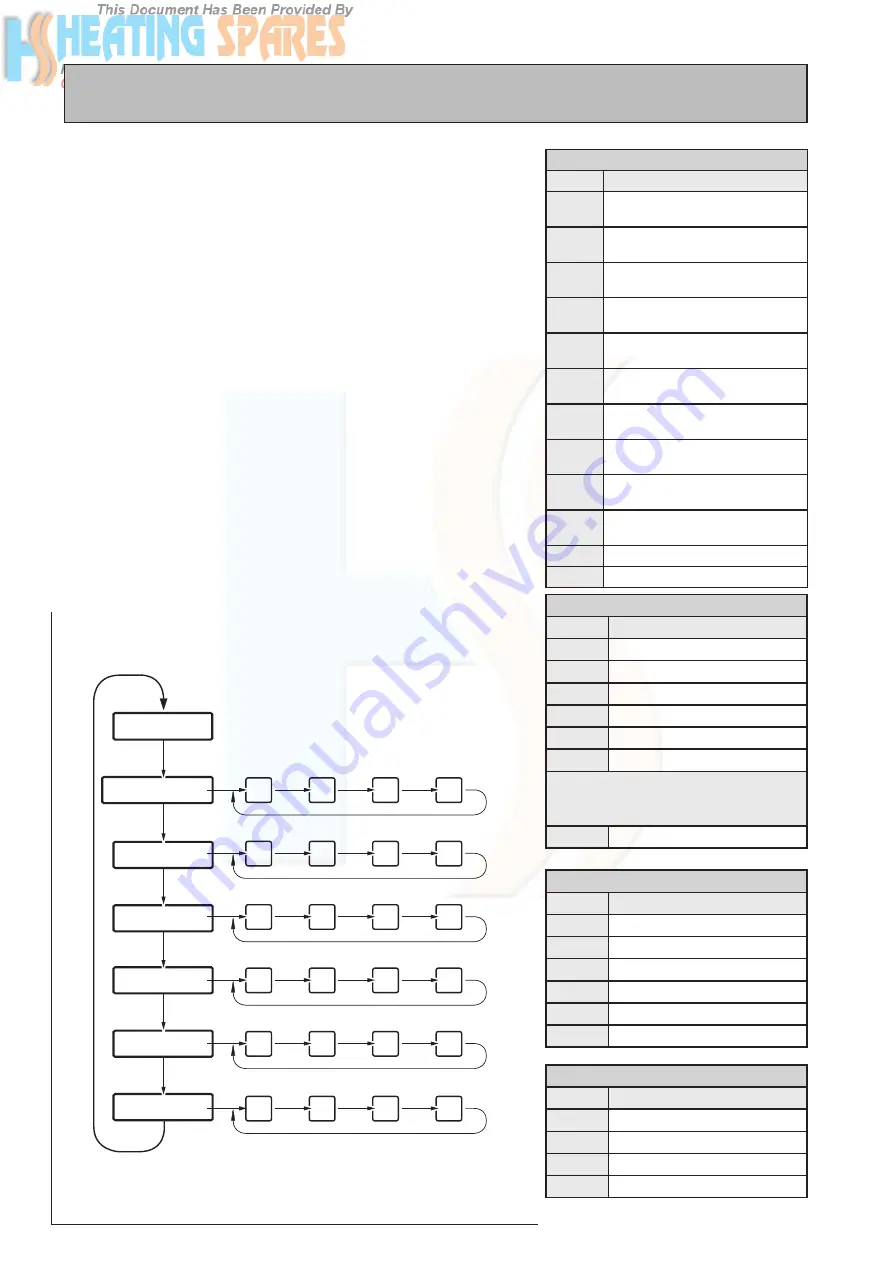
Figure 5.3 Display and push buttons on main PCB
COMMISSIONING
���������������������
���������������
������������������
����������������������������
����������������������
���������������
��������������
���������������
��
��
��
��
��
��
��
��
��
��
��
��
��
��
��
��
��
��
��
��
���������������
��������������������������
���������������
���������������������������
��������
��������
��������
��������
��������
��������
��������
��������
��������
��������
��������
��������
��������
��������
��������
��������
��������
��������
��������
��������
��������
��������
��
��
���
���
��������������
��������
��������
��������
��������
��������
��������
��������
(b) Temperature mode: In this mode the current temperature read by the selected
sensor is displayed. The button B1 is used to select this mode and the button B2
is used to select the appropriate sensor.
The temperature is indicated by alternatively flashing the sensor number and its
temperature reading or the error code. For example if sensor S1 is selected and
the temperature reading is 90
o
C, then the display will flash to indicate ‘S1’ and
‘90’. If the temperature sensor is faulty, then the display will flash to indicate ‘S1’
and ‘EN’ when EN is the error code. The error code will be as follows:
E1 – Open circuit
E2 – Short circuit
E3 – Temperature >99
o
C
The sensors used in this appliance are described in table 5.5.
(c) Set point mode: In this mode the set points used in the control of the appliance
are displayed. The button B1 is used to select the mode and the button B2 is
used to select the set-point. The set-point readings are displayed by alternatively
flashing the set-point number and its value. The set points which can be displayed
are shown in table 5.6.
(d) Fan speed mode: In this mode fan speeds used in control of the boiler are
displayed. The button B1 is used to select this mode and the button B2 is used
to select the appropriate fan speed reading.
The fan speed reading, in rpm, is displayed by alternatively flashing the fan
speed number ‘FN’ and the corresponding fan speed reading divided by 100.
For example preset ignition speed of 3222 rpm will be displayed by alternatively
flashing ‘F3’ and ‘32’. The fan speed readings available for this appliance are shown
in table 5.7. (Note: The fan speed i.e. appliance input can only be read but not
changed.)
Summary of Contents for GS A-Class 12/OV
Page 39: ...Supplied By www heating spares co Tel 0161 620 6677 Page 39 GULFSTREAM A CLASS ...
Page 40: ...Supplied By www heating spares co Tel 0161 620 6677 Page 40 ...
Page 41: ...Supplied By www heating spares co Tel 0161 620 6677 Page 41 GULFSTREAM A CLASS ...
Page 42: ...Supplied By www heating spares co Tel 0161 620 6677 ...
Page 43: ...Supplied By www heating spares co Tel 0161 620 6677 ...
Page 44: ...Supplied By www heating spares co Tel 0161 620 6677 ...


