Supplied By www.heating spares.co Tel. 0161 620 6677
Page 25
GULFSTREAM
A-CL
ASS
5.5 CONTROL PANEL, DISPLAY & DIAGNOSTICS
The appliance controls fitted to the GulfStream
A-CLASS
have been designed to be fully
automatic and to provide functional and diagnostic information to the installer/
commissioning engineer.
5.5.1 Appliance model identification
In order to comply with the latest gas safety regulations, this appliance is fitted with
a model identification resistance. The controller reads this ID tag and compares it
with the appliance code set on the controller. The two must match for the appliance
to function. If there is a mismatch, the appliance will shut down safely and flag the
error message ‘33’ on the display.
The appliance ID data is shown in table 5.2 and the procedure for setting the appliance
code if a controller is replaced is described in section 5.5.3 (h)
(Warning: Under no circumstances should the appliance ID resistor be changed or
tampered with).
Table 5.2 Appliance ID data
Model
Appliance code
Appliance ID resistor
12 OV/SP
10
1K
20 OV/SP
20
1K5
30 OV/SP
30
2K2
If the boiler develops a fault (indicated by flashing red indicator light i.e. Led 3) then
proceed as follows:
1. If the red light is flashing
(a) Press button 1 to reset and return to gas boiler operatIon
(b) If the red light switches off - the fault has been cleared
(c) If the red light flashes again after 2 minutes - the fault has not been cleared.
Go to 2 below.
2. If the red light is still flashing
(a) Press button 2
(b) If the red light switches on permanent - the ‘switch’ electric backup has been
selected. Pressing button 2 again will deselect the ‘switch’.
(c) If red light continues flashing - ‘switch’ electric backup cannot be used.
Table 5.3: Description of front panel controls
LED
Status
Function indication
Led 1
(green)
ON
Control circuit power supply is on
OFF
Control circuit power supply switched off or faulty
Led 2
(yellow)
OFF
Gas boiler in standby mode i.e. burner is off
FLASHING
Gas boiler is in ignition phase
ON
Flame has been sensed and the gas boiler (i.e. burner) is on
Led 3
(Red)
OFF
Gas boiler is in standby mode i.e. healthy
FLASHING
Boiler requires resetting e.g. lockout fault has occurred. (See below)
ON
Electric backup boiler has been selected (See below)
Push Button
1
Used to reset gas boiler and clear faults
2
Used to select ‘Switch’ electric backup
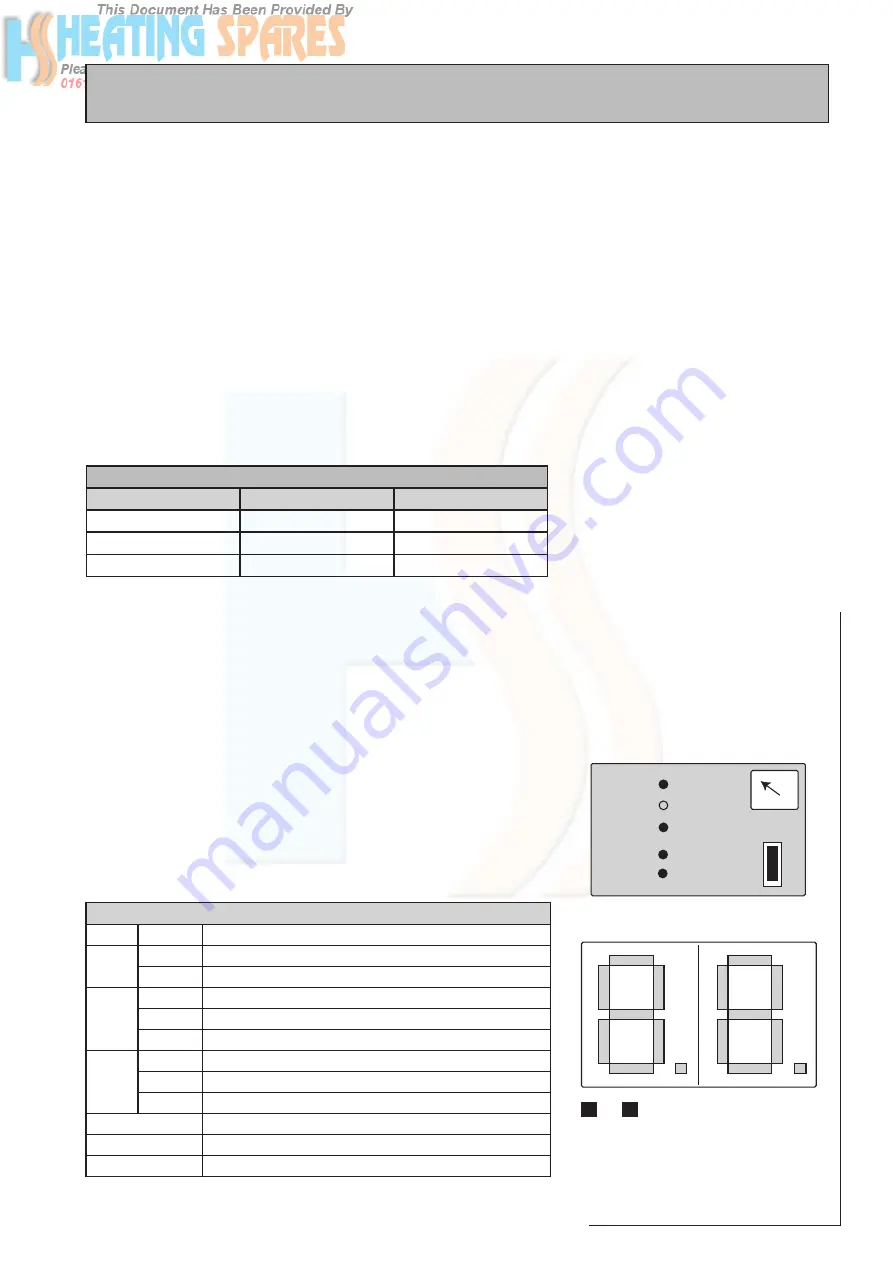
Figure 5.1: Front panel display
Figure 5.2 Display and push buttons on main
PCB
COMMISSIONING
�����
�����
�����
��������
��������
��������������
����������������
��
�
�
�
�
�
d1
D1.4
D1.7
D1.1
D2.4
D2.7
D2.1
D1.6
D1.5
D1.2
D1.3
D2.6
D2.5
D2.2
D2.3
d2
B1
B2
Figure 5.2 Display and push buttons on main PCB
5.5.2 Front Panel Controls
The operation of the appliance is indicated on
the front panel (figure 5.1) by green, yellow and
red indicator lights (LEDs). The push buttons
1 and 2 are used to reset the boiler and to
switch the backup electric boiler on /off in the
event of a gas boiler failure. The functions of
the front panel controls are described below
in table 5.3.
If the electric backup boiler has been selected,
(indicated by permanently ON Red Led_3). The
user can switch the electric backup boiler ON
and OFF by pressing Button_2. To permanetly
switch the electric boiler off and select the gas
boiler, switch OFF by pressing Button_2 and
then press Button_1.
5.5.3 Main PCB Functions & Diagnostics
The controller functions and faults are indicated
on the 2 digit display mounted on the main PCB
and the display functions are selected by the
push buttons B1 and B2 (figure 5.2). The flow
chart of the display mode is shown in figure 5.3.
The display functions are described below: -
(a) Normal mode: In this mode the display
(figure 5.2) is used to indicate the status
of different input demands and output
functions. The first left hand digit is used to
indicate demands sensed by the controller
and the second right hand digit indicates
the output functions of the controller.
This mode is selected by button B1 and the
display description is presented in table
5.4.
Summary of Contents for GS A-Class 12/OV
Page 39: ...Supplied By www heating spares co Tel 0161 620 6677 Page 39 GULFSTREAM A CLASS ...
Page 40: ...Supplied By www heating spares co Tel 0161 620 6677 Page 40 ...
Page 41: ...Supplied By www heating spares co Tel 0161 620 6677 Page 41 GULFSTREAM A CLASS ...
Page 42: ...Supplied By www heating spares co Tel 0161 620 6677 ...
Page 43: ...Supplied By www heating spares co Tel 0161 620 6677 ...
Page 44: ...Supplied By www heating spares co Tel 0161 620 6677 ...


