background image


No

. 96-1886-01E 


Rev

1.1 

GTECH Aircon Radio (Model GWT154)


PAGE  


53


OF


 72 

5 Address: 

0x2F 

0x2E 

0x2D 

0x2C 

0x2B 

0x2A 

0x29 

0x28 

Address: 

0x37 0x36 0x35 0x34 0x33 0x32 0x31 0x30 

7 Address: 

0x3F 

0x3E 

0x3D 

0x3C 

0x3B 

0x3A 

0x39 

0x38 


Address: 

0x47 0x46 0x45 0x44 0x43 0x42 0x41 0x40 

9 Address: 

0x4F 

0x4E 

0x4D 

0x4C 

0x4B 

0x4A 

0x49 

0x48 

10 

Address: 

0x57 0x56 0x55 0x54 0x53 0x52 0x51 0x50 

11 Address: 

0x5F 

0x5E 

0x5D 

0x5C 

0x5B 

0x5A 

0x59 

0x58 


12 

Address: 

0x67 0x66 0x65 0x64 0x63 0x62 0x61 0x60 

13 Address: 

0x6F 

0x6E 

0x6D 

0x6C 

0x6B 

0x6A 

0x69 

0x68 

14 

Address: 

0x77 0x76 0x75 0x74 0x73 0x72 0x71 0x70 

15 Address: 

0x7F 

0x7E 

0x7D 

0x7C 

0x7B 

0x7A 

0x79 

0x78 


16 

Address: 

0x87 0x86 0x85 0x84 0x83 0x82 0x81 0x80 

17 Address: 

0x8F 

0x8E 

0x8D 

0x8C 

0x8B 

0x8A 

0x89 

0x88 

18 

Address: 

0x97 0x96 0x95 0x94 0x93 0x92 0x91 0x90 

19 Address: 

0x9F 

0x9E 

0x9D 

0x9C 

0x9B 

0x9A 

0x99 

0x98 


20 Address: 

0xA7 

0xA6 

0xA5 0xA4 0xA3 0xA2 0xA1 0xA0 

21 Address: 

0xAF 

0xAE 

0xAD 0xAC 0xAB 0xAA 0xA9  0xA8 

22 Address: 

0xB7 

0xB6 

0xB5 0xB4 0xB3 0xB2 0xB1 0xB0 

23 Address: 

0xBF 

0xBE 

0xBD 0xBC 0xBB 0xBA 0xB9  0xB8 


24 Address: 

0xC7 

0xC6 

0xC5 0xC4 0xC3 0xC2 0xC1 0xC0 

25 Address: 

0xCF 

0xCE 

0xCD 0xCC 0xCB 0xCA 0xC9  0xC8 

26 Address: 

0xD7 

0xD6 

0xD5 0xD4 0xD3 0xD2 0xD1 0xD0 

27 Address: 

0xDF 

0xDE 

0xDD 0xDC 0xDB 0xDA 0xD9  0xD8 


28 Address: 

0xE7 

0xE6 

0xE5 0xE4 0xE3 0xE2 0xE1 0xE0 

29 Address: 

0xEF 

0xEE 

0xED 

0xEC 

0xEB 

0xEA 

0xE9 

0xE8 

30 Address: 

0xF7 

0xF6 

0xF5 0xF4 0xF3 0xF2 0xF1 0xF0 

31 Address: 

0xFF 

0xFE 

0xFD 

0xFC 

0xFB 

0xFA 

0xF9 

0xF8 


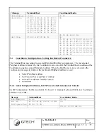
Structure 37: GTECH485 Peripheral Address Filter Mask 

7.2.2.23


Reserved (0x16) 

7.2.2.24


Reserved (0x17) 

7.2.2.25


Get Ping (0x18) 

Polls the Coordinator radio for any response to a Host CPU Send Ping.  Replies with Length = zero(0) 
if no Ping response has been received. 
 

Bytes: 

1 1 1 1 1 

Summary of Contents for GWT154

Page 1: ...empt from disclosure under applicable law This document shall not be modified reproduced copied or transferred without proper prior authorization from GTECH Proprietary Notice applies to all pages APP...

Page 2: ...tics 13 3 7 Host Board Electrical Characteristics 15 3 8 GWT154 Recommended Configurations 15 3 9 RF Module Operation 17 3 10 Setting Compliance Limits When Using Host Software 20 4 0 Wireless Network...

Page 3: ...twork Start and Joining 59 9 2 Coordinator Configuration Setting Firewall Address Mask 63 9 3 Coordinator Configuration Get End Device Statistics 64 9 4 Coordinator Configuration Setting End Device Pa...

Page 4: ...lottery terminal for initialization and authorization of End Device peripherals This allows GTECH the ability to integrate the local security measures with field service installations and manufacturin...

Page 5: ...Reset on Break support in accordance with 3 o USB 2 0 Type B Mini o Internal 3 3V UART The following form factors are supported o Pinned module For new embedded designs or as an OEM module replacement...

Page 6: ...e Dongle Optional for legacy products o Plastic Parts 16 2104 502E 16 2105 502E o Dongle Label 14 2027 01E Wall mount Power Supply Optional for legacy products o US 50 0347 01E o UK 50 0347 02E o EU 5...

Page 7: ...No 96 1886 01E Rev 1 1 GTECH Aircon Radio Model GWT154 PAGE 7 OF 72 Figure 1 Block Diagram 3 3 Radio Module Pin Definitions The communication between the Host board and the Radio module is via UART...

Page 8: ...ging of radio module CC2530 9 DTR_N Data Terminal Ready communication line 10 GROUND Ground 11 NC No Connect 12 CTS_N Clear to Send Flow Control 13 SLEEP_N Module status indicator 14 NC P1_6 UTX1 No C...

Page 9: ...No 96 1886 01E Rev 1 1 GTECH Aircon Radio Model GWT154 PAGE 9 OF 72 3 4 Mechanical Drawings Figure 3 Radio Module 1 0 x 1 33 antenna option not shown Figure 4 Host Board with Radio Module 1 6 x 2 25...

Page 10: ...uire any soldering when mounting it to a board 3 5 1 New GTECH Embedded Applications or OEM Replacement Modules For new designs the footprint design on the host carrier board will depend on the host c...

Page 11: ...er connection It uses two 10 pin receptacles to receive the Radio Module The receptacles used on the Host Board are manufactured by Samtec CUI Inc and TYCO Several other manufacturers provide comparab...

Page 12: ...No 96 1886 01E Rev 1 1 GTECH Aircon Radio Model GWT154 PAGE 12 OF 72 Figure 7 Radio Module mounted to the Host Board Figure 8 Dongle Assembly Top and Bottom view...

Page 13: ...6 Radio Baud Rate 250 kbps Radio Chip Rate 2 Mcps Table 3 General Radio Characteristics Parameter Min Typical Max Unit Conditions Receiver Sensitivity 99 95 85 dBm 1 PER 802 15 4 2006 Receiver Maximum...

Page 14: ...uency 40 40 ppm 40 C to 80 C Table 5 RF Transmit Specifications At 25 C 3 3VDC unless noted Parameter Limit Conditions Minimum Operating Bandwidth 500kHz Peak Output Power 1W Antenna Gain Derating Lim...

Page 15: ...Output Voltage 3 3 3 3 6 Volts Table 8 Power Supply Parameter Min Typical Max Unit Serial Baud Rate 2 4 19 2 230 4 kbps Input Supply Power 5 12 Volts Input Supply Current 300 mA Table 9 RS 485 Serial...

Page 16: ...odified RS485 peripheral with the GWT154 OEM module replacement 3 Installation of an existing USB Serial peripheral running GTECH 485 Packet Protocol into a legacy terminal 4 Installation of a new USB...

Page 17: ...cated to each Coordinator radio By operating the serial host interface at a higher data rate than the GTECH485 s original 19 2Kb the latency introduced by packet buffering within the radio modules can...

Page 18: ...does not include dedicated UART Break detect hardware but the Coordinator radio firmware will monitor the GTECH485 bus for a UART Break condition In addition the Host CPU may issue a Break command pa...

Page 19: ...with their joined network as soon as they are powered up The TIMAC will issue an 802 15 4 Beacon Request on every channel enabled and wait to see if it receives a response from its PAN Coordinator If...

Page 20: ...list of settable transmit output power levels Refer to Table 11 Compliance Limits for setting up the proper compliance limits RF Channel Max Host RF Power Value dBm TX_PWR Register Value RF Output Po...

Page 21: ...riptor list is at maximum the End Device will sequentially unicast an Associate Request to each of the PAN Coordinators found in the Descriptor list and wait for a response If it does not receive a re...

Page 22: ...to the Coordinator secured using the new network key The Short address and network key are saved in non volatile memory when the MAC layer Acknowledge is received Upon receiving the Join PAN response...

Page 23: ...No 96 1886 01E Rev 1 1 GTECH Aircon Radio Model GWT154 PAGE 23 OF 72 Figure 11 Pairing Sequence...

Page 24: ...UI 64 and PIN a Debug Lock bit is permanently set in Flash that prevents further access to the Flash memory image via the In System Programming ISP interface Only the CHIP_ERASE command may be execute...

Page 25: ...NULL The End Device radio s Peripheral addressed by the broadcast SYN address packet will reply with the appropriate response packet The Coordinator radio upon receiving a SYN response packet from an...

Page 26: ...ice Address NULL Connect End Device Address Source Disconnect End Device Address NULL Figure 12 End Device Address Selection 5 2 Data Security The CCM security protocol within 802 15 4 will be used to...

Page 27: ...es This may be performed by the Host CPU or the radio s application layer Fragmentation requires additional overhead with each 802 15 4 packet that will reduce the maximum packet payload length 1 2 3...

Page 28: ...roposed Radio module method Serial data from the Host CPU to the Coordinator radio is buffered until the entire packet up to 544 bytes is received before beginning the RF transfer The radio does not b...

Page 29: ...to 10 8ms up to 3 retries length bytes received ACK 43 4us Xmit ACK 1Byte 1 2ms to 10 8ms up to 3 retries length bytes received Note Failure to receive any ACK suspends further MAC packet transmission...

Page 30: ...The maximum safe payload is derived from packets using extended addresses and PANs Networks using short addressing have the option of reallocating the unused extended address bytes to the payload fie...

Page 31: ...No 96 1886 01E Rev 1 1 GTECH Aircon Radio Model GWT154 PAGE 31 OF 72 1 125 0x7D 13 n 80 1 126 0x7E 14 n 80 1 127 0x7F 15 n 80 1 1 Length 80 END n Length Table 12 Fragmentation Codes...

Page 32: ...e used to indicate the start of a dedicated radio command packet This protocol character would need to be reserved for radio configuration packets in all future versions of the GTECH485 protocol A mor...

Page 33: ...erially from left to right beginning with byte 1 7 1 2 GTECH Protocol Control Characters The following table lists the special character codes used by the GTECH485 protocol to identify message type an...

Page 34: ...re limited to a range between 0x21 and 0xFF By default if a peripheral receives an address packet with an address other than its own it is to un assert itself from the bus The 802 15 4 radio module wi...

Page 35: ...prior SYN packet s address value A successful response message is encapsulated in an RF packet and returned to the Coordinator radio In the event of a timeout or invalid response message no RF respons...

Page 36: ...18 Escape Character Insertion Referring to Error Reference source not found the UART receive process is reset to the idle state The protocol characters ACK NAK CAN and SI are encapsulated and unicast...

Page 37: ...e 19 Escape Sequencing State Machine 7 2 Wired Interface Infrastructure 7 2 1 Radio Set up and Configuration The Coordinator radio is controlled by the Host CPU by encapsulating configuration messages...

Page 38: ...spontaneously transmits a packet over the Host serial interface The Radio should reply to all Host CPU data packets when it is the addressed peripheral By definition all Host CPU configuration packets...

Page 39: ...equest like Join Request Bit 6 Reserved should be set to zero 0 Bits 5 to 1 Radio configuration commands see Error Reference source not found below Bit 0 Direction when zero 0 the command packet is re...

Page 40: ...dBm Antenna Sel Sets the transmit power antenna for the currently selected End Device 0x14 Get Periph Addr Mask 32 Bit mapped address mask Gets the current Peripheral address filtering mask contents 0...

Page 41: ...ctive 0x05 End Device attempting to re join PAN 0x20 Coordinator network idle 0x21 Coordinator network started 0x22 Coordinator network joining is accepting new End Devices 0x23 to 0x7F Reserved 0x80...

Page 42: ...Device stop requesting to join a PAN 0x31 Enable Joining If Coordinator mode respond to associate requests from End Device radios 0x32 Request Joining If End Device begin issuing periodic associate r...

Page 43: ...nables that channel to be scanned Channel bits set to zero 0 are skipped during the scan When powering up or after a reset the End Device will always scan the channels in the channel mask for its asso...

Page 44: ...PAN ID Default 0x0000 7 2 2 7 Get Energy Scan 0x06 Returns a list of Received Signal Strength Indication RSSI for all 802 15 4 2 4GHz channels found by the radio When initially commissioning an 802 15...

Page 45: ...st of PAN Descriptors for every PAN Coordinator that responds During network commissioning the Host CPU can use the PAN Descriptor list to identify a suitable channel for the new PAN The format of the...

Page 46: ...an Associate Request while the Coordinator radio When the Coordinator is enabled to join new End Device to its network and it receives Association Requests from one or more devices the following infor...

Page 47: ...d Device as obtained from the Get Device List response packet EUI 64 Extended Unique Identifier MAC Address for the End Device as obtained from the Get Device List response packet Network Key Optional...

Page 48: ...d Returns the EUI 64 and Short address of the currently selected End Device used to tunnel GTECH485 protocol messages between the Terminal and Peripheral on the selected radio Bytes 1 1 2 8 Field 0x0E...

Page 49: ...containing the Address and peripheral Status response bytes Bytes 1 1 1 8 Field 0x0F Code 9 Length 0x00 Type EUI 64 Address Structure 29 Set End Device Address Request Packet Extended Address EUI 64 A...

Page 50: ...evice BAUD Device 0x00 Currently selected End Device radio 0x01 Coordinator radio 0x02 to 0xFF Unused Reserved BAUD 0x00 230 400 0x01 115 200 0x02 76 800 0x03 38 400 0x04 19 200 0x05 9 600 0x06 4 800...

Page 51: ...safe timeout period in seconds 7 2 2 20 Set RF Configuration 0x13 Sets the signed 8 bit Transmit power setting and Antenna select for the Coordinator or currently selected End Device radio Bytes 1 1 1...

Page 52: ...ices with their corresponding mask bit set true 1 in the Peripheral Address Mask Attempts to select End Devices that are blocked by the filter bit set to 0 disconnects the Coordinator from any previou...

Page 53: ...4 0x93 0x92 0x91 0x90 19 Address 0x9F 0x9E 0x9D 0x9C 0x9B 0x9A 0x99 0x98 20 Address 0xA7 0xA6 0xA5 0xA4 0xA3 0xA2 0xA1 0xA0 21 Address 0xAF 0xAE 0xAD 0xAC 0xAB 0xAA 0xA9 0xA8 22 Address 0xB7 0xB6 0xB5...

Page 54: ...test packet to the addressed or selected End Device If and End Device radio is not selected or fails to respond to the ping packet an Acknowledge will not be returned to the Host CPU When a Send Ping...

Page 55: ...Packets Received Structure 42 Loopback Test Result Packet 7 2 2 30 Set Loopback Mode 0x1D Selects a loopback mode for diagnostic and compliance test purposes Bytes 1 1 1 Field 0x1D Code 1 Length Mode...

Page 56: ...broadcast a configuration message to all End Devices in its PAN forcing them perform a hardware Reset and assert a hardware Break condition on each End Device s EIA485 serial bus as part of its startu...

Page 57: ...s and indicates this by flashing the LED at a 500ms ON and 500ms OFF cadence If and when while attempting to Associate the radio receives a beacon from a Coordinator in response to its beacon request...

Page 58: ...No 96 1886 01E Rev 1 1 GTECH Aircon Radio Model GWT154 PAGE 58 OF 72 through GTECH Technical Training and Support Services 401 392 7961...

Page 59: ...a configuration sequence Get RSSI results After the Terminal User has selected a suitable channel the radio may be configured Set Mode to Coordinator Set Channel Mask and Default Channel Set Mode to S...

Page 60: ...C0 F5 C0 1B E5 38 1B E5 01 00 4B 1B ED 00 E1 07 00 00 21 04 9 1 3 Set Peripheral Address Start RSSI Energy Scan Set energy scan Message Terminal Host Coordinator Radio SYN Address 16 01 01 00 Set Ene...

Page 61: ...D 04 9 1 6 Set Peripheral Address Set Start Network Mode Set Mode Start Network Message Terminal Host Coordinator Radio SYN Address 16 01 01 00 Set Mode 05 00 01 01 20 DE 04 06 05 00 81 00 7F 04 9 1 7...

Page 62: ...s EUI selected from the ACL join an End Device to the network Join PAN Short Address 0x0001 EUI 64 0 18 75 0 1 26 56 37 Message Terminal Host Coordinator Radio SYN Address 16 01 01 00 Join PAN 05 00 0...

Page 63: ...ess and communicate with an End Device Peripheral it must write the Coordinator s Firewall Address Mask The Mask may be optionally saved to persistent memory by issuing the NV Save Mode Send Address F...

Page 64: ...Peripheral wired to it Once selected the Coordinator End Device link is maintained until the Terminal Host addresses a different Peripheral Link quality and End Device 802 15 4 addressing may be obtai...

Page 65: ...tor Configuration Setting End Device Parameters The Terminal Host may adjust the selected Peripheral End Device parameters The last selected Peripheral address is retained by the Coordinator radio eve...

Page 66: ...1 01 00 Set RF Configuration 05 00 1B EE 02 01 03 E9 04 06 05 00 91 00 6F 04 9 5 Peripheral Configuration Status Joining an End Device radio to a PAN may be performed entirely by using the radio modul...

Page 67: ...e in a residential installation This equipment generates uses and can radiate radio frequency energy and if not installed and used in accordance with the instructions may cause harmful interference to...

Page 68: ...impedance is 50 ohms List of all Antennas Acceptable for use with the Transmitter 1 2 4 GHz chip antenna Johanson part number 2450AT18A100 2 2 4 GHz dipole antenna for reverse polarity SMA connector...

Page 69: ...AT18A100 2 2 4 GHz Antenne dip le pour connecteur SMA invers la polarit le nombre LS cadre de la recherche 001 0001 a C ble de montage 105mm de longueur avec la cloison de polarit invers e SMA femelle...

Page 70: ...ditions above are met further transmitter testing will not be required However the OEM integrator is still responsible for testing their end product for any additional compliance requirements required...

Page 71: ...ample of an End Product Label Figure 22 Example of a Model GWT154 Radio Module Label The OEM of the GWT154 Radio Module must only use the approved antenna s listed above which have been certified with...

Page 72: ...rs GTECH Center 10 Memorial Boulevard Providence RI 02903 USA 401 392 1000 Website http www gtech com Technical Support Ted Carr Sr Product Compliance Specialist 401 392 7721 Online Customer Service h...

Reviews: