background image


GTE Industrieelektronik GmbH 


   Tel. +49 2162 3703-0 

Helmholtzstr.21, 38-40 


   Fax +49 2162 3703-25 

41747 Viersen 


   E-mail: [email protected] 

GERMANY 


   Internet: www.gte.de 
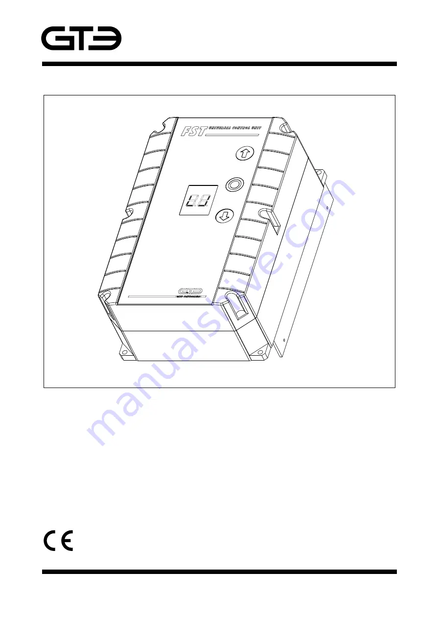
FST-75 

FST-150 

This document is subject to change without notification!


260-2210-002 EN064 

FST 75 / 150


Operating Instructions 


- Translation - 


Frequency Converter Control Unit for  

sectional doors, roller doors, high-speed doors, roller-grilles, 

sliding gates, hinged gates, folding doors and barriers 


Summary of Contents for FST-150

Page 1: ...e de GERMANY Internet www gte de FST 75 FST 150 This document is subject to change without notification 260 2210 002 EN064 FST 75 150 Operating Instructions Translation Frequency Converter Control Unit for sectional doors roller doors high speed doors roller grilles sliding gates hinged gates folding doors and barriers ...

Page 2: ...he motor 12 Maximum voltage boost 12 Safety Photocell in close direction function 12 Positioning 13 Set final open position only in connenction with DES 13 Set final close position only in connection with DES 13 Set partial opening only in connection with DES 13 Switching position Relay K3 Adjustment only available with DES 13 Switching position Relay K4 Adjustment only available with DES 13 Setti...

Page 3: ...ontact edge closing contact 21 Typ 3 Fraba system optical contact edge 21 Safety device in opening direction 21 Timer for close 1 22 Closing after release 2 NVZ 22 Start up delay 22 Dead man control 22 Radio control Rope switch 22 Partial opening 22 Manual automatic operation 23 Running time control 23 Interlock system 23 Cycle counter 23 Relays 23 Level adjusment only in connection with DES 23 Co...

Page 4: ... Safety against permanent commands e g defect switches Reversing delay Functions Soft start and soft coasting that conserves material Step by step function for 1 channel radio control Automatic closing after time Automatic closing after passing through Function for permanent operation Manual automatic operation Photo electric cell function with safety function and time reset Safety edge function w...

Page 5: ...ll of the instructions and warnings contained in these operating instructions The modification or conversion of the FST 75 150 control unit is only permissible upon prior consultation with the manufacturer The operational safety of the supplied FST 75 150 control unit is only guaranteed if it is used in the manner prescribed The limit values given in the technical specifications may not be exceede...

Page 6: ...ut off device such as a main circuit breaker which at each pole provides a contact gap which is in compliance with the conditions set forth in Overvoltage Category III for full disconnection must be attached to the permanently laid installation A risk analysis must be performed The customer must ensure that the rolling gate the sliding gate or the lifting element is protected and that no hazardous...

Page 7: ... the value to less than 30 Speeds For the FST 75 150 operate at its optimum best and perform all of the required functions the control unit must be aware of the rated frequency of the connected motor The rated frequency must be set before all other work and settings are performed under menu item 05 default setting 50 Hz Where required or requested the desired speeds for the slow speed closing and ...

Page 8: ...safety edges are activated Cycle counter After setting the FST 75 150 parameters or having completed the initial operation or maintenance work it is recommended that you register the cycle number which denotes when the last amendment occurred Menu 93 Safe operation depends among other things on the FC being set properly Any third party manipulation may result in damage to property and personal inj...

Page 9: ...ions of mechanical limit switches Warning The set up run occurs at 50 Hz in dead man operation mode It starts with a ramp a Set the rated frequency of the motor in Menu 05 factory default setting 50 Hz b Move the door with the internal open button into the required final position open Stop near to the required end position Then restart with soft start into the final position open c Fix the final o...

Page 10: ... start into the final position open Upper segment displays will flash c Press the internal STOP button for approx 3 seconds until the display changes The open position is now saved d Move the door with the internal close button Stop near to the required end position Then restart with soft start into the final position close Lower segment displays will flash e Press the STOP button for approx 3 sec...

Page 11: ...d press to select The display will switch to the main menu 4 Quit program mode Turn the rotary switch until the figure 00 appears in the display and then press the rotary switch Number codes Menu structure Explanations Certain menu items are only available in connection with the respective components When using a DES other menus automatically become activated There are 3 types of menu structures a...

Page 12: ...ernal key or key pad in the event of an error occurring in the safety device 0 2 The safety edge close How it works save 1 Without reverse 2 With reverse 1 second after open Press rotary switch W 3 With reverse up to open position 0 3 The safety edge open How it works save 1 Without reverse W 2 With reverse 1 second after close Press rotary switch 3 With reverse up to close position 0 5 Rated freq...

Page 13: ...re the final close position is reached can be shifted to open or close by setting a value 0 9 Shift position to open by x values Press rotary switch _ 0 9 Shift position to close by x values 1 6 Set partial opening only in connection with DES Save Use the internal keys to go to the desired partial opening position Stop key 1 7 Switching position Relay K3 Adjustment only available with DES Save Use...

Page 14: ... Time setting 1 90 seconds Starts after passing the photo cells In connection with Menu 23 2 4 Closing 2 automatic locking through photo cells Save w 0 Closing deactivated Press rotary switch 1 90 Time setting 1 90 seconds Starts after passing the photo cells In connection with Menu 23 2 5 Radio control cable switch Save 1 IMP inside Open Close IMP outside Open Close Press rotary switch 2 IMP insi...

Page 15: ...n of safety device in opening direction Save w 0 No safety device 1 1 normally closed contact i e photo cell 1k2 without testing 2 2 normally closed contacts i e photo cell 1k2 without testing 3 1 normally open contact i e electrical safety edge 8k2 4 2 normally open contacts i e electrical safety edge 8k2 Press rotary switch 5 1 System Raytector or OSE 6 2 Systems Raytector or OSE 7 1 System phot...

Page 16: ...justable range max 200 Hz Press rotary switch 4 3 Speed for swifter closing only in connection with DES save w 0 15 100 Closing with x Hz To disable function set value to 0 The changeover is enabled by programming the position DES s Menu 44 Press rotary switch 4 4 Switch point for lowering the closing speed only in connection with DES save Use the internal keys to go to the required position Stop ...

Page 17: ...anent contact from intermediate stop position or programmed switch point see 51 3 Traffic light function red 4 Traffic light function green Press rotary switch 5 Position indicator open 6 Position indicator close 7 Flashing light function 8 Beacon 9 Fault alarm F 1 3 Safety circuit DES F 1 4 Emergency off contact actuated F 2 5 Closed safety edge 8k2 defective F 2 7 Closed pressure wave edge 1k2 d...

Page 18: ...the safety strips is operated between positions no failure 15 Impulse 1 second with open command e g for light controllers 16 Traffic light function red is off at close position 2 8 Relay K4 See sub menu 2 7 save R elays K5 K8 5 5 Relay K5 See sub menu 2 7 save 5 6 Relay K6 See sub menu 2 7 save 5 7 Relay K7 See sub menu 2 7 save 5 8 Relay K8 See sub menu 2 7 save ...

Page 19: ... of way 2 Right of way without preference Press rotary switch 3 Right of way with preference from inside 4 Right of way with preference from outside 6 2 Extension of green phase time Save w 0 90 Setting of Extension time in sec Press rotary switch 6 3 Time of prewarning Save w 0 10 Setting of prewarning time in sec Press rotary switch 6 4 Doorway evacuation time Save w 0 90 Setting of doorway evac...

Page 20: ...8 Delayed closing Save W 0 Delay deactivated 3 50 Time setting 3 50 seconds Starts after closing command Press rotary switch In combination with a relay i e for delayed opening this function allows the operation of a all round light as opening warning In case of double winged or overlapped doors an appropriate forerun may be activated 8 5 Setting of service interval Save W 0 Function service inter...

Page 21: ...n on DES is used to initiate the test function After premature shut down shortly before reaching the final close position a period of 2 seconds will count down Within this time it is necessary to actuate the system by touching down the contact edge This actuation tests whether the pressure wave edge is intact It is then possible to perform a run Type 2 Self monitoring contact edge closing contact ...

Page 22: ...iggered If an advance warning time has been set in close an advance warning will also be made upon automatic closing The function may be useful for overlapped turning doors or in case of a previous activation of a bolting device In this cases a combination with a relay is necessary control of traffic light or bolting device Dead man control The door will only operate for as long as the command is ...

Page 23: ...l with advance warning can be used However it is also possible to provide two OPEN position indicators for example This is especially useful for meeting special requirements WARNING Please observe the maximum load of the relays Under certain circumstances it may be necessary to fuse protect the circuit Level adjusment only in connection with DES The function cannot be applied to pneumatic systems ...

Page 24: ...t By overlaying the graduation lines in the left hand segment it is possible to see how far the digit sequence has run The first graduation line is for digit 1 the second for digit 2 and so on The digits written one after another in the right hand segment represent the number of cycles as a figure Example 0003526 for 3526 cycles Press adjusting knob 9 2 Display of the last 2 errors Selection F Upo...

Page 25: ...50 Call the menu function 9 7 In the sub menu the digits 0 0 are displayed By using the opening and closing buttons the stored software versions on the SD card are scrolled in the display The actual software version is displayed in the LED display Using the Stop button the chosen software version is loaded While loading a loading signal is displayed circular turning light that may pause for a whil...

Page 26: ...afety edge is activated twice in a row during closing Check whether any obstacles are in the vicinity of the door or whether a line has been disconnected in the connecting lead or the connecting lead has short circuited Perform the closing operation until the end position close is reached F 2 4 Close safety edge 8k2 activated Check the activation of the safety edge The connecting lead may have sho...

Page 27: ...ating without control Weight to high F 5 9 Running time error The normal running time for a complete run is exceeded The drive is blocked Slip clutch too loose or defective The limit switch is not yet adjusted see Troubleshooting F 6 2 Safety device in opening activated Check the connection of safety device in opening direction for disconnection F 6 3 Safety device in opening defect Testing of saf...

Page 28: ...he running speed of the door slows automatically The brake resistance is loaded too often Error F 46 is displayed The running speed of the door is too high Reduce the speed or install an FC with a higher performance Run time error F 59 upon initial operation Travel distance set too short Spacing between limit switches set too short upon delivery for example Switch the control unit off and then on ...

Page 29: ...mA 10 Wiring of inputs Use only floating contacts Supply for external power consuming devices Voltage output V 24 DC max power demand mA 500 Relay outputs Relay outputs Type of output Potential free 2 xchangeover 4 x normally open max switching current A ohmic load 1 Parameter settings Door speed Hz 10 200 Creep speed Hz 10 50 Rampe time 1 3 1 0 5 Sec 2 1 Sec 3 2 Sec Break initiation Break initiat...

Page 30: ...er supply Motor brake Motor cable Plug and play motor cable GfA GTE Limit switches external command keys Signal relays e g for traffic lights Safety edges OPEN direction External command keys 24VDC power supply for external devices max 500 mA Safety edges CLOSE direction Internal command keys Connector for sluice function SLF Connector for status message function SMF Interface for memory card SD M...

Page 31: ...150 260 2210 002 EN06 8 switch mains G1 Rectifier Y1 Brake 230VDC Y1 Brake 105VDC 10A F1 power supply for external loads 230VAC In addition a fuse must be installed to protect this circuit Remove bridge 2 3 Place bridge 2 3 Fuse max 16A using rectifier standard For motor with brake 230V Power supply 230V 50Hz G1 X1 L N X2 PE PE 1 2 For motor with brake 105V Y1 Y1 N L 4 3 6 5 1 X2 3 4 2 5 6 optiona...

Page 32: ... Control Unit FST 75 150 260 2210 002 EN06 8 PE W U V W PE 1 2 3 4 PE PIN Cable No U V Pin assignment Motor in delta connection Motor in delta connection 3 x 230V PE 3 x 230V PE Shielded cable U V W M1 M1 PE X3 U PE PE W V optionally X4 PE Shielded cable U V W Connect cable shield only to the control not to the motor Connect cable shield only to the control not to the motor ...

Page 33: ...CLOSE direction Safety Photocell Select manual automatic Deactivates the automatic time based closure Manual operation is possible Emergency stop Select full intermediate Intermediate OPEN Intermediate stop or full open ATTENTION Fire Alarm Panel Safety systems are deactivated Configurable impulse evaluation Menu 2 5 Remote control Rope switch inside Remove terminal bridges before wiring X5 1 2 4 ...

Page 34: ... close Close Open ZH Intermediate stop S Safety Limit switch arrangement Th Thermal switch VZ S Open ZH S Close S Th R Open R Close S Th 1 2 3 5 6 4 1 2 3 4 5 6 5 6 7 8 9 10 Safety circuit In Signal B GND Signal A Safety circuit Out 8V DC optionally X6 Connection for drives with limit switches DES digital limit switch DES Application of motors with Pin assignment 23 Note Remove bridge 17 21 if con...

Page 35: ...tor position indicator Configuration of relays with aid of FST menu K3 K4 Control panel outside Optional connection outside K5 K6 K7 K8 red green red green Traffic outside Traffic inside L1 N Radio remote control or cable traction switch Contact sequence is selectable open stop close or open close by menu 2 5 Terminals 17 18 24VDC power supply for external loads 500mA max 3 1 2 5 4 6 X7 13 15 16 1...

Page 36: ...ed gold using normally opened contacts Protection OPEN direction using normally closed contacts Photocells or pneumatic savety edges Connect enclosed resistor 1K2 in series with contact Resistor color code brown red red gold 2nd FRABA optical safety edge green white brown 21 22 24 using safety photocells with testing Protection OPEN direction Receiver 2 Transmitter 1 Transmitter 2 Receiver 1 using...

Page 37: ...1K2 resistor FRABA optical safety edge brown white green Protection CLOSE direction Protection CLOSE direction Door contact Pedestrian pass door contact Pedestrian pass door contact Remove bridge when connecting Remove bridge when connecting Remove bridge when connecting Pneumatic safety egdes Connect 1k2 resistor in series with contact Resistor color code brown red red gold Self testing safety ed...

Reviews: