background image

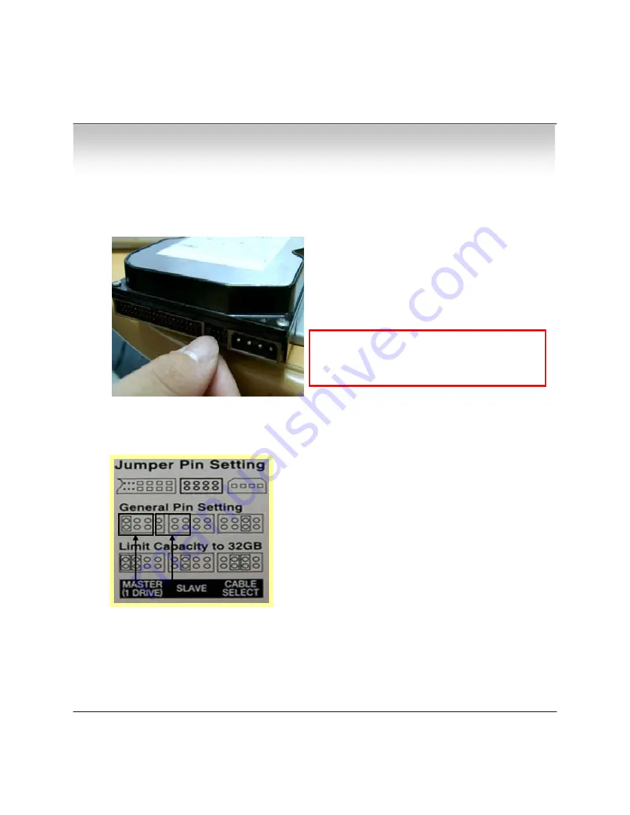
① Jumper Setup Master or Slave

10

3.1 Hard Disk Installation

• Refer to  Jumper Pin Setting on HDD Surface

• When HDD Installed, Fix jump as Master                         

1

and Connect Pin at the Left end of Jumper

!!Please use HDD which can supply higher than 

UDMA66

.!!

※ Example of Samsung HDD Jumper Setup

• Chapter 3 - Installation

• Jumper Setup as Master or Slave refer to Explanation 

of Surface Hard Disk

• Jumper is located at Hard Disk Data Cable or Rear        

1

Side of Hard Disk

• Hard Disk is Installed, Setup as Master               

1

When Hard Disk changing, it must be serviced

after System Off  (Power Button System Off).

If not, it

s a cause of Fatal Failure of HDD

Summary of Contents for GLM-154

Page 1: ...LCD DVR COMBO Model GLM 154 USER S MANUAL Firmware Version 2 4 Revision Date 2005 03 25...

Page 2: ...nection 11 3 4 Network Connection 11 3 5 Alarm Relay PTZ Connection 12 3 6 System initial START Power Connection 13 Hard Disk Format 13 CHAPTER 4 Display 4 1 System Power ON 14 4 2 Select Screen Mode...

Page 3: ...itle Setup 27 6 3 2 Covert PTZ Setup 27 6 3 3 Color Setup 28 6 4 AUDIO 28 6 4 1 Audio Recording Setup 28 6 4 2 Live Audio Setup 29 6 5 ALARM 29 6 5 1 Alarm Input Setup 29 6 5 2 Relay Output Setup 30 6...

Page 4: ...Division Selection 40 7 1 3 PTZ Control 40 7 1 4 Selection Network ID 40 7 1 5 AVI File Conversion 41 7 1 6 Color Adjustment 41 7 2 Search 7 2 1 Function Introduction 42 7 2 2 Search Method 43 7 2 3...

Page 5: ...r Data System Recovery After Power Failure Remote Pan Tilt Zoom Focus Iris Remote Control Remote Live Viewing Remote Playback and Remote File copy Playback Network Transmission Recording Triplex opera...

Page 6: ...Accessories GLM 154 Set Remote Controller User s Manual AAA Battery X 2 DC12V Adaptor Power Cord Packing Components 5 Please confirm accessories when you open packing box Installation CD ROM Camera s...

Page 7: ...System Organization 1 4 External Organization of System 6 Remote Client PC Image Printer NETWORK Alarm Sensor 1 4 Relay Out GLM 154 Camera 1 4 Video In Video Out TCP IP Alarm Input Out Remocon Monitor...

Page 8: ...ode for Searching Recorded Video PTZ Focus Go to Camera PTZ Focus Control Remote Controller Sensor Input Refer to using of remote controller Search Controller Volume Control Search Recorded video Cont...

Page 9: ...onitor Ethernet TCP IP Connect Port for LAN Cable Possible to Remote Survey to Connect to Client Alarm Relay RS 485 Connect Port for Sensor Relay PTZ Pan Tilt Zoom DC Power Input Terminal Power is Sup...

Page 10: ...ion If there are many DVRs at the same place they are operate together when press remote controller Channel Select Button 4ch Available 1 4 Button POWER System ON OFF MENU Open menu RETURN Cancel Setu...

Page 11: ...h can supply higher than UDMA66 Example of Samsung HDD Jumper Setup Chapter 3 Installation Jumper Setup as Master or Slave refer to Explanation of Surface Hard Disk Jumper is located at Hard Disk Data...

Page 12: ...Connect Camera at Multi Jack Modular Port in Back Side Panel 3 3 Monitor Connection Connect Monitor Out of GLM 154 to Another Monitor Input 3 4 Network Connection Connect Ethernet Terminal to Network...

Page 13: ...DC12V Adaptor ALARM Alarm Input Terminal IN1 IN2 IN3 IN4 GND Connect Sensor Input of Channel and GND Connect Ground cable RELAY Alarm Output Terminal NO NC COM After Checking Alarm Output Type Connec...

Page 14: ...d Disk System Can t Recognize the HDD So there s the Same Situation without HDD Please Format HDD when Insert New HDD Only Screen Display is Possible Work Menu and Search are impossible 2 New HDD Form...

Page 15: ...after Finishing Installation Tip Check System Condition using LED POWER Showing System On Off RECORD Showing Record On Off NETWORK Showing Client Connection Status ALARM Lighting when Sensor Alarm Ac...

Page 16: ...trol Camera PTZ Pan Tilt Zoom Focus Only Useable for Proper Camera Press PTZ FOCUS Button to Open PTZ Menu at Right Under Side and Control by Search Controller Press PTZ FOCUS Button Second Time to Op...

Page 17: ...ontroller When Press PTZ FOCUS Button by Turns Focus IRIS Preset Swing Menu will Appear at the Right Under Side and possible to Control by Search Controller PRESET NUMBER 1 NUMBER CHANGE UP DOWN SET F...

Page 18: ...1 Button or F1 Button on Remote Controller To Move to Saved Location Press Front Panel Key Button No 2 or F2 Button on Remote Controller SWING MODE PAN SWING NUMBER CHANGE UP DOWN FIELD CHANGE LEFT R...

Page 19: ...Manager Operator and Network 1 Administrator Possible All Function Access System On Shutdown Setup Search 2 Manager Possible System On and Search 3 Operator Possible System On 4 Network Possible Conne...

Page 20: ...ssible to Search Recorded Date Time Move Cursor to Select Date of Calendar Recorded Date Time are Indicated by Gray Color Press Enter to Open Selected Date Recorded Time Appear to Under Side Press Ent...

Page 21: ...during the Selected 1 Period Motion Searching Motion Detected Event during 1 the Selected period Timer Searching Schedule Change or Recording 1 Setup Change Event System Searching Power On Off Event...

Page 22: ...nd Network Password is 1234 Showing Password as Asterix Method of Changing Password MENU 6 System 4 Password Only Watch Mode can go to Menu Search PTZ Focus Mode can t move to Menu Initial Menu Displa...

Page 23: ...ode 5 Border Color Select Border Line Color White Blue Red Yellow Green and Gray 6 Sequence Dwell Setup Rotation Cycle Time 1 60 Sec when 4CH Rotation Mode at Watch Mode 7 De interlace Mode Remove Scr...

Page 24: ...TSC 352 240 120fps 704 240 60fps 704 480 30fps PAL 352 288 100fps 704 288 50fps 704 576 30fps Possible to Setup Size Rec Rate Quality per Each Channel When Applying Change Setup Press Enter 1 When Can...

Page 25: ...ion as Partially Move to Partial 1 Range Setup Press Enter After Partial Range Setup 1 to Finish Region Setup Pre Motion Duration Setup Pre Motion Duration Time 1 1 5 sec Post Motion Duration Setup Mo...

Page 26: ...ng Setup Exit Weekly mode Setup at Record Setup Scheduled Region Indicated Yellow After Deselect Schedule Activated Region by Press ENTER and Select Date Time to Move Cursor After Selecting Region and...

Page 27: ...and Setup Non Activate Region When Select Multi Region Using Direction Key in to Expand Non Activate Region Press Enter to Select Multi Non Activate Region Same Method as Possible to Expand Non Activ...

Page 28: ...No 0 9 1 Left Right Keys for Moving another Letter Camera Indicate Camera No to Setup Covert Setup Covert On Off What s Covert When Covert On Watch Mode Video Display is 1 Hidden but Recording is On P...

Page 29: ...orded Channel Camera Indicate Camera No to Setup Bright Control Monitor Bright Contrast Control Monitor Contrast Color Control Monitor Color Tint Control Monitor Tint All Setup Possible to Control 0 1...

Page 30: ...nsor Connection Status of Connected or Disconnected Camera Input Camera No 1 4 of connecting Alarm Type Alarm Sensor Type Normal Open or Normal Close Generally Alarm Sensor can be Divided Two Types 1...

Page 31: ...al Close Latched Transparent Latched When Sensor Alarm Activated Relay Reacted in Setup Duration Transparent Relay Reacted Temporary During Sensor Alarm Activate 6 6 1 Date Time Date Time Setup Date S...

Page 32: ...e well Press the NEXT button and progress the step Don t change the DDNS name because it is fixed the domain name IP Address Input IP Address Gateway Input Gateway IP for Internet Server Subnet Mask I...

Page 33: ...ect by 00115f00b5a7 dvrlink net at client program or Web you can connect the DVR 1 If your network connect at the router please must port forwarding 2 Please you must enter the exact IP address DNS Se...

Page 34: ...when Hard Disk Full Disk Error Alarm On when Hard Disk Error Key Input Setup Key Input Sound 6 6 4 Password Setup Password 6 6 4 1 Administrator Password Setup Menu System On Off Current Password Inpu...

Page 35: ...sword Re Confirm New Password Save Exit Applying New Password Current Password Input Current Password Initial Password 1234 New Password Input New Password Re enter the Password Re Confirm New Passwor...

Page 36: ...ss OK to Run Initialize If do Factory Default Every Setup is Initialized but 1 Saving Image is Not Erase Disk Overwrite Overwrite Permission when 1 Hard Disk Full O N Overwrite Hard Disk from Oldest D...

Page 37: ...M VGA Overlay YV12 Format Graphic Card All Radeon Nvidia Above Geforce Matrox Above G400 Compatible Video Card Above DIVX Codec 5 1 When Use Media Player DVR Remote Agent 1 0 Install Open CD ROM Driv...

Page 38: ...all DvrRemoteAgent 1 0 Recommend Basic setup c program files DvrRemote Agent 1 0 Click Next Showing Progress of Copy of Files Appear DirectX 7 0a Install Menu If DirectX Version Lower than 7 0a Press...

Page 39: ...When Finishing Installation System must be Restarted Click Yes Finish DvrRemoteAgent 1 0 Program Installation 38 Client...

Page 40: ...nt Time Date Search Move to Search Mode to Play Video Setup Move to Setup to Change Network Setup or Option I D Selection Select I D identification to Connect Server Connect Connect Server GLM 154 Dis...

Page 41: ...iew One Large Screen Mode Showing One by One 1 1 View 1 Depend on User Selection Time Not Work Screen Division Mode Full Screen View Present Video Move to Full Screen Mode Mouse Double Click when Retu...

Page 42: ...s Stop to Open Designating File Name Saving Location and Save AVI File Saved AVI File can Open Ordinary Moving Picture Player Moving Picture Player Codec Version is Above Divx 5 1 7 1 5 AVI File Conve...

Page 43: ...ation by Time Bar LIVE Return to Watch Mode SETUP Open Setup to Change Network Setup or Option Screen Division Selection Change Playing Screen Division Mode SEARCH Option Backup Video or Search Event...

Page 44: ...arch Controller in Recorded Area Indicate Camera Channel to Confirm Camera Recording Situation Refreshment Recording Information Situation Window by Camera Channel If Connected Channel is 5 or More An...

Page 45: ...ignate Backup Time Now or Later Designate Backup Date Time when Later Source Designate Backup Image Data Length to input Start Time End Time Channel Check Camera Channel for Backup Select All or Desel...

Page 46: ...Backup File for 2 ch Apr 13 17H30M 17H35M Indicate Present Playing Video Camera Channel No Indicate Present Time Date and Possible to Search Time Date Search Controller The Same Way of Previous Searc...

Page 47: ...g Playing Video Designate File name File Type JPG or BMP and Location and Finally Press Saving Conversion and Saving Image from Remote Viewer Print Image Present Image Capture and Print Out Image Duri...

Page 48: ...No Indicate Event Log Order No Max Event Log No of 1 Page is 100 CH Indicate Event Occurred Camera No Date Time Indicate Event Occurred Time Date Description Indicate Event Detail Description Left Dir...

Page 49: ...ate Event Occurred Order No CH Indicate Event Occurred Camera No Date Time Indicate Event Occurred Time Date Description Indicate Event Detail Description Go to timelane After Select Event Move Search...

Page 50: ...r Connecting Server New Click to Input New ID Information Add After Input All ID Information Add ID Information at ID Status Modify After Amend All ID Information Applying Change ID Information Remove...

Page 51: ...ed Only when Connect as Administrator DVR System Setup Possible to Control Almost Every Setup at the Remote When Activate Setup or Changing Setup at the DVR Server 1 It s Impossible to Change Setup at...

Page 52: ...a Covert 1 Function PTZ Protocol Tip Refer to DVR Server Setup for Each Setup Detail Record Setup Record Size Rate Quality Setup Setup Each Channel 1 Resolution Compression Rate Timer Recording Setup...

Page 53: ...1 Alarm Connection Type Relay Output Setup Setup for Each Channel 1 Relay Connection Mode System Setup System Info Possible to Watch DVR System Status Buzzer Setup Setup DVR Buzzer Sound On Off Passw...

Page 54: ...Input IP Address for DVR Server at the Internet Explorer Address Input Place When Appear Active X install Message Please Click Confirm or Continue Showing Web Client Window at Internet Explorer Click...

Page 55: ...ut DVR IP or URL Address Port DVR Client Connection Port is 6100 ID Select ID Administrator Manager Operator No Difference Authority on Web Client Password Input Password Only Possible to Monitoring L...

Reviews: