GSi PNEG-1707 Operation Manual Download Page 8

1. Safety

8

PNEG-1707

 TM-Series Tower Dryer

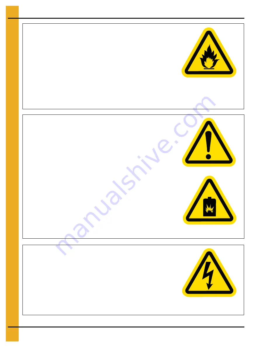
Install and Operate Gas-Fired Equipment Properly

• 

Gas-fired equipment should be installed by a qualified pipe 

fitter and must conform with local codes.

•     For Canada: The equipment shall be installed in accordance 

with the 

Natural Gas and Propane Installation Code, CSA 

B149.1, or the Propane Storage and Handling Code, CSA 
B149.2,

 or applicable provincial regulations, which should be 

carefully followed in all cases. Authorities having jurisdiction 
should be consulted before installations are made.

•     For the United States: The equipment shall be installed in 

accordance with the 

National Fuel Gas Code ANSI 

Z223.1/NFPA 54.

ST-0016-2

For Your Safety

• 

If you smell gas: 

- Do not try to light any appliance.

- Extinguish any open flames.

- Do not touch any electrical switch.

- Immediately call your gas supplier. Follow the gas supplier’s 

  instructions.

- If you cannot reach your gas supplier, call the fire department.

• 

The use and storage of gasoline and other flammable vapors and 

liquids in open containers in the vicinity of this appliance is 
hazardous.

• 

Improper installation, adjustment, alteration, service or maintenance 

can cause property damage, injury or death. Read the installation, 
operating and maintenance instructions thoroughly before installing 
or servicing this equipment. Installation and service must be 
performed by a qualified installer, service agency or the gas 
supplier.

ST-0024-1

Install and Operate Electrical Equipment Properly

• 

Electrical controls must be installed by a qualified electrician 

and must meet the standards set by the National Electric Code, 
Canadian Electrical Code, and all local and state codes.

•     Lock-out power source before making adjustments, cleaning, or 

maintaining equipment.

ST-0027-2

Summary of Contents for PNEG-1707

Page 1: ...TM Series Tower Dryer Operation Manual PNEG 1707 Version 2 1 Date 09 22 20 PNEG 1707...

Page 2: ...Tower Dryer All information illustrations photos and specifications in this manual are based on the latest information available at the time of publication The right is reserved to make changes at an...

Page 3: ...e Layout 21 Central United States Foundation Plan 22 Northern United States Foundation Plan 23 Fuel Supply 24 Electrical Power Supply 25 Transformers and Wiring Voltage Drop 25 Power Supply Disconnect...

Page 4: ...cy 42 Chapter 8 Dryer Operation 43 Dryer Start up 43 Dryer Shut Down 44 Moisture Control Setup 45 Chapter 9 Drying Time Tables 49 Drying Time Table Model 1008 49 Drying Time Table Model 1010 50 Drying...

Page 5: ...ust stay out of the work area at all times Alterations must not be made to the equipment Alterations can produce dangerous situations resulting in SERIOUS INJURY or DEATH This equipment must be instal...

Page 6: ...s symbol indicates an imminently hazardous situation which if not avoided will result in serious injury or death This symbol indicates a potentially hazardous situation which if not avoided can result...

Page 7: ...damage personal injury or loss of life Carefully read all safety messages in this manual and safety signs on your machine Keep signs in good condition Replace missing or damaged safety signs Be sure n...

Page 8: ...ouch any electrical switch Immediately call your gas supplier Follow the gas supplier s instructions If you cannot reach your gas supplier call the fire department The use and storage of gasoline and...

Page 9: ...d repair before further operation ST 0030 2 Exercise Caution When Drying Flammable Grains Be aware that some grains are highly flammable including but not limited to rapeseed canola linseed sunflower...

Page 10: ...er protective clothing and equipment at all times All guards must be in place before and during operation Images of guards removed in this manual are for illustration purposes only Use caution when wo...

Page 11: ...t smoke or use naked flames Lock out and tag out power supplies and fuel supplies to all equipment Do not work alone Work in teams of at least three so that help is immediately available in the event...

Page 12: ...Off Sheet Below is a sign off sheet that can be used to verify that all personnel have read and understood the safety instructions This sign off sheet is provided for your convenience and personal re...

Page 13: ...mergency Stop switch is located on the upper control box door Pushing the Emergency Stop switch will interrupt the control power and stop all dryer functions Emergency stop Pushing the Emergency Stop...

Page 14: ...ry conveyors are matched to dryer metering capacities 12 DO NOT operate in an area where combustible material will be drawn into the dryer 13 The operating and safety recommendations in this manual pe...

Page 15: ...mption IL 62510 Phone 1 217 226 4421 A free replacement will be sent to you NOTE Decals are not shown actual size DANGER DANGER DC 1224 High voltage Will cause serious injury or death Lockout power be...

Page 16: ...hen dryer is running DC 1063 GSI Group Inc 217 226 4421 DC 1064 High speed belt drive operating overhead Can cause serious injury Keep head and hands clear Do not enter when dryer is running WARNING G...

Page 17: ...0 624 798 972 Maximum Cool Holding BU 246 246 289 289 Minimum Cool Holding BU 144 144 187 187 Dryer Holding BU 1049 1223 1397 1571 Outside Catwalks 1 2 3 3 BPH 20 15 Maximum Cooling 800 1000 1200 1500...

Page 18: ...r Dimensions Figure 3A M 1008T Figure 3B M 1010T M 1008T Five 5 sections total usually ships on two 2 trucks all five 5 sections are 10 10 in diameter M 1010T Six 6 sections total usually ships on two...

Page 19: ...ns Continued Figure 3C M 1012T Figure 3D M 1015T M 1012T Seven 7 sections total usually ships on three 3 trucks all seven 7 sections are 10 10 in diameter M 1015T Eight 8 sections total usually ships...

Page 20: ...id Propane LP Dryers with Internal Vaporizers Liquid Draw The dryer is designed to operate on liquid propane with liquid draw from the supply tank A piping system is provided on the dryer including st...

Page 21: ...4 Dryer Installation PNEG 1707 TM Series Tower Dryer 21 Modular Base Layout Figure 4A...

Page 22: ...4 Dryer Installation 22 PNEG 1707 TM Series Tower Dryer Central United States Foundation Plan Figure 4B...

Page 23: ...4 Dryer Installation PNEG 1707 TM Series Tower Dryer 23 Northern United States Foundation Plan Figure 4C...

Page 24: ...upply Figure 4D Liquid Propane LP Fuel Supply Figure 4E Natural Gas N Fuel Supply NOTE See table on Page 25 for recommended line size Connection to natural gas manifold on dryer NOTE See table on Page...

Page 25: ...tor starting and operating voltage Voltage drop during motor starting should not exceed 14 of normal voltage and after motor is running at full speed it should be within 8 of normal voltage TM 1008 TM...

Page 26: ...e Fan 40 94 141 200 Metering System 1 DC 5 Unload Auger 3 8 4 Auxiliary 1 10 28 460V 3 Phase Fan 40 47 76 150 Metering System 1 DC 5 Unload Auger 3 4 2 Auxiliary 1 10 14 TM 1010 230V 3 Phase Fan 50 11...

Page 27: ...s good contact with the surrounding soil making a proper ground 5 Connect the bare copper ground wire to the rod with proper clamp 6 Connect ground wire to control panel with the ground lug provided i...

Page 28: ...tractors transformers fuses or other electrical components found in the control or power box Turn the main disconnect handle located on the power box to the OFF position prior to servicing any of the...

Page 29: ...ng system and the unload auger ON or OFF and also selects the operation of the metering system In the MANUAL position the metering system operates at the speed set by the Metering Roll Speed Rotary sw...

Page 30: ...the left side of the Operation screen the operation animation shows the status of the fan heaters load and unload augers and meter rolls It will also display the grain temperature moisture content M...

Page 31: ...t takes for the dryer to refill Note that the computer will display the time required to fill the dryer on the previous load operation to aid you in setting an accurate time If the dryer runs out of g...

Page 32: ...e timer set point displayed in the time display Touching Cancel will exit the Modify Timer Set Point screen without saving any changes and the timer will stay at the currently saved set point Once you...

Page 33: ...displayed next to the Grain Temperature button The grain temperature set point is used for the temperature based moisture control only Modifying a temperature set point is much like setting a timer de...

Page 34: ...veral different parameters that can be modified on this screen Figure 6E 1 Drying mode Touching the Drying Mode button will display the select Drying Mode window Continuous flow will be the only optio...

Page 35: ...unload rate is exceeded Touching the Plenum Temperature Manager will display a Configuration screen that will allow you to turn this feature ON or OFF Also a configuration section is presented so that...

Page 36: ...Calibrate moisture sensor Touching this button will display the Configuration screen to adjust the offset for wet and dry moisture and temperature Figure 6I 7 Extended setup Touching this button will...

Page 37: ...e If you have the temperature set point at 180 and you select 3 as the burner differential then the burner will switch to low heat at 183 and back to high heat at 177 To modify a burner differential s...

Page 38: ...on the dryer reads 900 bushels then touch the Decrease button until the calibration reads 90 or if you ran a1000 bushels and the counter reads 1100 bushels then touch the Increase button until the cal...

Page 39: ...utton will display the Dryer Hardware Setup window In order for the dryer operate properly the following items must be entered correctly model number and fuel type Touch the select button until a chec...

Page 40: ...h will illuminate indicating that the dryer is ready to be started Start Switch Push the Dryer Start switch and all the selector switches on the control panel will be activated Fuel Check If using LP...

Page 41: ...y starting the fan Adjust the plenum temperature set point to 140 F 60 C On LP fired dryers open the liquid shut off valve and the manual shut off valve On NG fired dryers open the manual shut off val...

Page 42: ...flame 3 Close the fuel valve at the dryer and press the Dryer Power Stop button 4 Turn OFF the control power 5 Turn OFF the safety disconnect handle on the front of the power box and turn OFF the mai...

Page 43: ...for adjusting the out of grain timer 8 Open the main fuel valve on the propane tank or the natural gas fuel supply line Open all manual fuel shut off valves on the dryer 9 Turn the Fan switch to the...

Page 44: ...ation see moisture control setup section on Page 45 Dryer Shut Down 1 To turn the dryer off at the end of the day turn the Heater switch OFF the Load Auger switch OFF and the Unload Auger switch OFF 2...

Page 45: ...l Setup 1 To setup the moisture control first press the Setup button on the dryer touch screen See Figure 8B Figure 8B 2 Press the M C Setup button on the Setup screen See Figure 8C A screen entitled...

Page 46: ...sture The Variable option works best if the incoming moisture to the dryer is fairly consistent The 5 Speed option works best for changing incoming moisture levels To activate either press the appropr...

Page 47: ...to AUTO in either the Variable or 5 Speed mode will ensure a more accurate dryer unload control 7 The parameters for 5 Speed operation are preset for typical dryer operation They can be modified if d...

Page 48: ...r unload is operating in the automatic mode it may be necessary to limit the maximum and minimum unload rate on the dryer s metering system To accomplish this press the Unload Parameters button on the...

Page 49: ...0 270 23 15 180 210 250 180 210 240 24 15 160 190 220 160 190 210 25 15 140 170 200 140 170 190 26 15 130 150 180 130 150 170 27 15 120 140 160 110 130 150 28 15 100 120 140 100 120 140 29 15 90 110 1...

Page 50: ...13 160 180 200 140 160 180 23 13 130 140 160 110 130 150 25 13 100 120 130 90 100 120 Divider Set for Maximum Heat Area Divider Set for Minimum Heat Area Moisture 170 F Unload Rate 190 F Unload Rate 2...

Page 51: ...18 13 290 320 350 270 300 330 19 13 250 280 310 230 260 280 20 13 220 250 230 200 230 250 21 13 200 220 240 180 200 220 23 13 160 170 190 160 160 180 25 13 130 140 150 120 130 140 Divider Set for Max...

Page 52: ...290 340 400 280 320 370 24 15 260 310 350 250 290 330 25 15 230 280 320 220 260 300 26 15 210 250 280 200 230 270 27 15 190 220 260 180 210 240 28 15 170 200 230 160 190 210 29 15 150 180 210 150 170...

Page 53: ...0 320 21 13 240 270 300 220 250 290 23 13 190 220 240 180 200 230 25 13 150 170 190 140 160 180 Divider Set for Maximum Heat Area Divider Set for Minimum Heat Area Moisture 170 F Unload Rate 190 F Unl...

Page 54: ...580 18 13 430 470 520 410 450 490 19 13 370 410 450 350 390 430 20 13 330 360 330 310 340 380 21 13 290 320 350 280 310 340 23 13 230 260 280 250 240 270 25 13 190 210 230 180 200 220 Divider Set for...

Page 55: ...e sections on the tower dryers must be in place and clamped down at all times when the dryer is in operation If the cover is off during operation the vacuum created by the blowers will suck foreign ma...

Page 56: ...slide gates at the bottom of each column as well as easy access gates located near the hopper discharge area permit fast dumping of each individual grain column If it is necessary to emergency dump gr...

Page 57: ...rain and trash from unload section of dryer ___ Open emergency grain discharge doors ___ Open drain valve in gas train ___ Cover burner with a tarp or plastic sheeting Lubrication Table Location Instr...

Page 58: ...s of Airflow This error message is displayed when airflow air pressure has been established but was lost for some reason This could happen if while during the dryers operation the grain has settled or...

Page 59: ...on happens during the initial ignition of the burner If the burner fails to light check to make sure that the gas has been turned ON and or the maxon valve has been turned ON The reference to the numb...

Page 60: ...if this safety looses 12 VDC to terminal J1 04 on the Input Output board Push the Red button on the overload to reset this error This is caused from the motor operating with to much of a work load wh...

Page 61: ...ontinuous flow to the staged batch position while the dryer is running in the continuous flow mode To avoid this shut down stop the dryer before switching modes Press stop to clear the error Network F...

Page 62: ...ould have a open connection Plenum Temp Short This error indicates there is a shorted condition with the plenum temperature sensor located inside the plenum chamber This could be a shorted sensor or t...

Page 63: ...DESIGN OF SUCH PRODUCTS The sole and exclusive remedy for any claimant is set forth in this Limited Warranty and shall not exceed the amount paid for the product purchased This Warranty only covers th...

Page 64: ...refully followed in all cases Authorities having jurisdiction should be consulted before installations are made GSI Group 1004 E Illinois St Assumption IL 62510 0020 Phone 1 217 226 4421 Fax 1 217 226...

Reviews: