RR 620 CD / RR 650 CD
Allgemeiner Teil / General Section
GRUNDIG Service
1 - 3
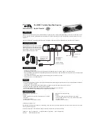
Schutzlötstelle
protective soldered joint
Laseranschlußplatte
Laser PCB
Technische Daten
Spannungsversorgung:
Netzbetrieb ................................................................ 230V, 50/60Hz
Batteriebetrieb ................................. 8 Monozellen 1,5V (R20, UM1)
Verstärkerteil:
Ausgangsleistung (DIN 45324, 10% THD):
Musikleistung ......................................................................... 2 x 4W
Sinusleistung ...................................................................... 2 x 2,6W
Stereo-Kopfhörer-Klinkenbuchse ........................................ 3,5mm ø
Rundfunkteil:
Wellenbereiche ................................................... FM: 87,5 - 108MHz
MW: 526,5 - 1606,5kHz
LW: 148,5 - 283,5kHz
Zwischenfrequenzen ...................................... 10,7MHz und 465kHz
Antennen .................................................... Teleskopantenne für FM
eingebaute Ferritstab-Antenne für MW/LW
Cassettenteil:
Tonträger .................................. Compact-Cassette nach DIN 45516
Spurlage ...................................................... Viertelspur international
Bandgeschwindigkeit ..................................................... 4,76cm/sec.
Motor ..................................................................... Gleichstrommotor
Frequenzübertragungsbereich .................................... 125Hz - 8kHz
Geräuschspannungsabstand ..................................................... 45dB
Gleichlauffehler ........................................................................ 0,35%
Automatik ............................ Aussteuerungsautomatik bei Aufnahme
Automatisches Auslösen der Tasten am Bandende
CD-Teil:
Frequenzübertragungsbereich .................................... 20Hz - 20kHz
Geräuschspannungsabstand ..................................................... 65dB
Technical Data
Power Supply:
Mains operation ......................................................... 230V, 50/60Hz
Battery operation ............................... 8 mono cells 1.5V (R20, UM1)
Amplifier Section:
Output power (DIN 45324, 10% THD):
Music power ........................................................................... 2 x 4W
Nominal power ..................................................................... 2 x 2,6W
Jack socket for stereo headphones ..................................... 3.5mm ø
Radio Section:
Wavebands ......................................................... FM: 87.5 - 108MHz
MW: 526.5 - 1606.5kHz
LW: 148.5 - 283.5kHz
Intermediate frequencies ................................ 10.7MHz and 465kHz
Aerials ......................................................... Telescopic aerial for FM
Built in ferrite rod aerial for MW/LW
Cassette Section:
Cassette .......................................... Compact cassette to DIN 45516
Track System ............................................. International quartertrack
Tape Speed ................................................................... 4.76cm/sec.
Motor .................................................................................. DC motor
Frequency Range ........................................................ 125Hz - 8kHz
S/N Ratio (weighted) ................................................................ 45dB
Wow and Flutter ....................................................................... 0.35%
Automatic ...................................... Automatic recording level control
Automatic button release at tape end
CD Section:
Frequency range .......................................................... 20Hz - 20kHz
S/N ratio, weighted ................................................................... 65dB
Service Hints
Cassette Section
Before commencing service work, ensure that the magnetic heads, the
capstan and the pinch roller are free from particles produced by tape
abrasion. The recording and playback levels and the tape run can be
improved by cleaning these parts with a cotton-wool tip soaked in spirit
or cleaning benzine.
If the heads or other components have been replaced, the technical
data of the recorder must be checked or adjusted according to the
values specified in the Service Manual.
CD Section
When removing the CD mechanism the Laser pick-up PCB must be
provided with a protective soldered joint before unplugging the connec-
tors to avoid damage to the Laser diode by static charges.
When inserting the new Laser pick-up the soldered joint fitted at the
factory must be removed after the connectors are plugged in.
Servicehinweise
Cassettenteil
Überprüfen Sie vor Beginn der Service-Arbeiten, ob die Magnetköpfe,
die Tonwelle und die Gummiandruckrolle frei von Bandabrieb sind.
Zum Reinigen dieser Teile verwenden Sie ein mit Spiritus oder
Reinigungsbenzin getränktes Wattestäbchen; dadurch verbessert sich
der Aufnahme- und Wiedergabepegel, sowie der Bandlauf.
Nach dem Ersatz von Magnetköpfen oder sonstiger Bauteile müssen
die technischen Daten des Gerätes anhand der im Service Manual
vorgegebenen Meßwerte überprüft bzw. eingestellt werden.
CD-Teil
Bei Ausbau des CD-Laufwerks muß vor Abziehen der Steck-
verbindungen eine Schutzlötstelle auf der Leiterplatte der Lasereinheit
angebracht werden, um eine Zerstörung der Laserdiode durch stati-
sche Aufladung zu vermeiden.
Beim Einbau einer neuen Lasereinheit muß nach Einstecken der
Steckverbinder die werkseitig angebrachte Schutzlötstelle entfernt
werden!