GRUNDIG Service
5 - 7
GV 27 …, GV 47 …, GV 7…
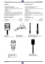
Laufwerk / Drive Mechanism
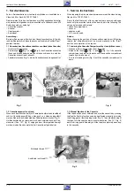
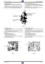
2.4 Kombikopf (Pos. 36)
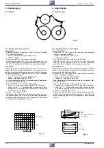
– Befestigungsfeder "A" (Fig. 14) und den Stecker abziehen.
– Montageschraube "B" herausschrauben und den Kombikopf aus-
tauschen.
– Beim Einbau die neue beigepackte Befestigungsfeder verwenden.
Nach dem Austausch des Kombikopfes sind alle Einstellungen wie
unter Punkt 3.1.2 und Punkt 3.2 angegeben durchzuführen.
2.4 A/C Head (combi head, Pos. 36)
– Remove fixing spring "A" (Fig. 14) and unplug the connector.
– Undo the mounting screw "B" and replace the A/C (combi) head.
– Use the new fixing spring delivered with the replacement A/C head
for reassembly.
After the A/C head has been replaced, all adjustments described in
para 3.1.2 and para 3.2 have to be carried out.
Fig. 15
Montageschraube B
Mounting screw B
Neigungswinkel-Einstellschraube
Tilt setting screw
A
Höhen-Einstellschraube
Height setting screw
Azimut-Einstellschraube
Azimuth adjustment
screw
Fig. 14
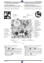
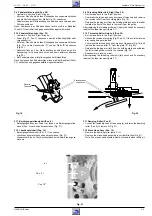
2.5 Fädelmotor (Pos. 38)
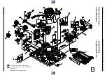
– Antriebsriemen (Pos. 39) entfernen (Fig. 15) und den Stecker des
Fädelmotors abziehen.
– Motorhalter (Pos. 40T) in Pfeilrichtung drücken und Fädelmotor
(Pos. 38) aus dem Motorhalter nehmen (Fig. 15).
Beim Einbau darauf achten, daß der Fädelmotor vorne und hinten
eingerastet ist.
2.6 Fädelmotorhalter (Pos. 40T)
– Fädelmotor ausbauen siehe Punkt 2.5.
– Capstanmotor ausbauen siehe Punkt 2.7.
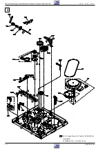
– Von unten die vier Sicherungsbolzen (A, Fig. 16) herausdrücken
und Motorhalter abnehmen.
Einbau in umgekehrter Reihenfolge.
2.5 Threading Motor (Pos. 38)
– Remove the drive belt (Pos. 39, Fig. 15) and unplug the connector
from the threading motor.
– Press the motor support (Pos. 40T) in the direction of the arrow and
take the threading motor (Pos. 38) out of the motor support (Fig. 15).
When fitting the motor ensure that the threading motor locks into the
front and rear bearing.
2.6 Threading Motor Holder (Pos. 40T)
– Remove the threading motor, para 2.5.
– Remove the capstan motor, para 2.7.
– Push out the four securing bolts (A, Fig. 16) from the bottom and
remove the motor holder.
Reassemble in reverse order.
38
39
40T
Fig. 16
A


