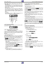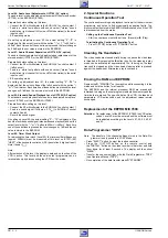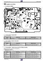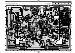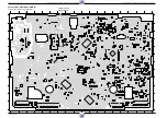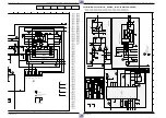
Adjustment Procedures
GV 27 …, GV 47 …, GV 7…
k
3 - 4
GRUNDIG Service
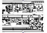
1.4 Chassis Board – Frontend (FV)
Test equipment: Oscilloscope with 10:1 Test Probe, Voltmeter, AF Millivoltmeter, Colour Generator
Service work after replacing the
… Tuner, IC7720, IC7721: Adjustments no. 2
… IC7720 (TDA9800T): Remove R3748
(PLL)
. The new TDA9800T automatically sets a "Default" value.
… IC7780: Adjustments no. 4, 5
Adjustment
Preparation
Adjustment Procedure
1. Demodulator Circuit
PAL, F5725
(AFC)
SECAM-L,
R3748
(Band I)
2. Delayed AGC
Voltage,
R3742
(AGC)
3. Residual Carrier
Band I,
F5721
(40.4MHz)
4. Stereo Level
5. Cross Talk
Voltmeter: ................................. IC7720-(15) or IC7721-(20)
EE-mode.
Colour generator 38.9MHz - 500mV
PP
: ...... Tuner 1701-(17)
Colour generator 33.9MHz / 500mV
PP
: ...... Tuner 1701-(17)
Press button "SYSTEM" repeatedly until "SEC" is displayed.
Feed in a PAL white test pattern with sound carrier (without sound
modulation, Ch27, 74dB
µ
V aerial signal) into the warmed-up VCR.
Oscilloscope: .............................................. Tuner 1701-(17)
EE-mode.
Colour generator 40.4MHz - 300mV
PP
: ...... Tuner 1701-(17)
Oscilloscope: ........................................................ F1720-(1)
EE-mode.
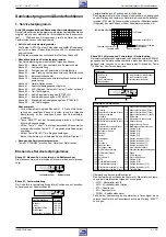
Call up the Service Test Programme (see page 2-4).
Call up Level 60 (see page 2-4).
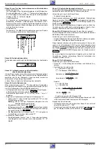
Call up the Service Test Programme (see page 2-4).
Call up Level 61 (see page 2-4).
Set the voltage with F5725
(AFC)
to 2.5V
±
0.2V.
Set the voltage with R3748
(Band I)
to 2.5V
±
0.2V.
Set the amplitude with R3742
(AGC)
to 550mV
PP
+0/-50mV.
Set the amplitude with F5721
(40.4MHz)
to minimum (5dB
lower at least than the input signal).
Observe the instructions for Level 60 (see page 2-6).
Terminate the Service Test Programme (see page 2-4).
Observe the instructions for Level 61 (see page 2-6).
Terminate the Service Test Programme (see page 2-4).
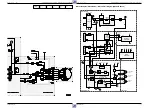
1.5 Chassis Board – Video/Chroma (VS, VS-S)
Test equipment: Oscilloscope with 10:1 Test Probe, Colour Generator
Service work after replacing the IC7007 or 7110: Adjustment no. 1
Adjustment
Preparation
Adjustment Procedure
The FMF signal must have an amplitude of 420mV
pp
. If the
value deviates by more than
±
40mV
pp
there is a technical
defect (e.g. IC7007).
Set Chroma signal with R3007
(PAL-Curr.)
to 160mV
PP
±
20mV
PP
(for 2-Head-VCR) or 130mV
PP
±
20mV
PP
(for 4-Head-VCR).
Set Chroma signal with R3159
(SECAM-Curr.)
to 210mV
PP
±
30mV
PP
.
Terminate the Service Test Programme, disconnect R3031
from L5001 and reassemble the drive mechanism.
Remove the drive mechanism (see page 1-9)
Call up the Service Test Programme – Level 10 (see page 2-4)
Feed in a PAL red raster test pattern with 75% saturation (ratio
burst: chroma = 1 : 2.2) into the AV1 socket and record it.
Oscilloscope: ................................ R3031 (T7006 – Emitter)
Connect R3031 (T7006 – Emitter) to L5001 (5VASW).
Oscilloscope: ................................................ R3007 – wiper
Feed in a PAL red raster test pattern with 75% saturation (ratio
burst: chroma = 1 : 2.2) into the AV1 socket and record it.
Oscilloscope: ................................................ R3159 – wiper
Feed in a SECAM-L red raster test pattern with 75% saturation
(ratio burst: chroma = 1 : 2.2) into the AV1 socket and record
it.
1. Chroma Recording
Current
PAL,
R3007
(PAL-Curr.)
SECAM-L,
R3159
(SECAM-Curr.)
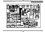
1.6 Chassis Board – Standard Sound (AL)
Test equipment / aids: Frequency Counter, AF Millivoltmeter, AF Generator, Colour Generator, branded Video Cassette.
Service work after replacing the RP-Head, L5603 or IC7007: Adjustment no. 1, 2
Adjustment
Preparation
Adjustment Procedure
With F5603
(BIAS R)
set the frequency to 70kHz
±
10kHz.
Set the voltage drop across R3600 with R3618
(BIAS)
to
15mV
rms
.
Check the frequency response.
The voltage ratio of 400Hz to 8kHz must not be higher than
1:0.7 or 0.7:1 (
±
3dB). If the voltage ratio exceeds these limits,
the bias must be altered:
To increase the playback voltage at 8kHz: Reduce "BIAS".
To reduce the playback voltage at 8kHz: Increase "BIAS".
Set output voltage with R3160
(PB-Lev.)
to 0.5V
rms
±
50mV.
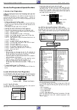
Observe the instructions for Level 62 (see page 2-6).
Terminate the Service Test Programme (see page 2-4).
Frequency counter: ....................... wire bridge 9034 (Head)
Record
AF millivoltmeter: .......................... BIAS1 or BIAS2 (R3606)
Record.
– Feed in a CCVS signal via EURO-AV1 socket, contact 20.
– Feed an audio signal of 200mV
rms
(480mV
PP
) from the AF
generator to the EURO-AV1 socket, contact 2 or 6.
– Make a recording of 400Hz and 8kHz each of 1 min at least.
Afterwards play back these recordings (MONO).
– Connect an AF millivoltmeter (oscilloscope) to EURO-AV1
socket, contact 1 or 3.
AF millivoltmeter: ............ EURO-AV1 socket, contact 1 or 3
AF generator (1kHz / 0.7V
rms
):
........................................ EURO-AV1 socket, contact 2 or 6
Feed in a CCVS signal via EURO-AV1 socket, contact 20.
Play back the self made recording (Normal Play).
Call up the Service Test Programme (see page 2-4).
Call up Level 62 (see page 2-4).
1. Erase Frequency,
F5603
(BIAS R)
1.1 Bias, R3618
(BIAS)
1.2 Frequency
Response Test
2. Playback Level for
Mono VCR,
R3160
(PB-Lev.)
for Stereo VCR

