background image

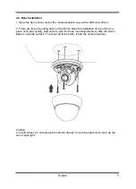
4.2. Base Installation

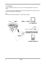
1. Open the dome cover ring at the marked position (e.g. with a flat screw driver).

2. There are three mounting holes on the Dome Base for installation of the unit in any 
place such as a ceiling, wall and etc. Use the three mounting screws to affix the Dome 
Base to a sturdy surface. To access all three holes, rotate the camera module.

Caution:
To avoid smear, do not expose the camera directly to a strong light source such as the 
sun or spot light.

5

English

Summary of Contents for GCA-B3322D

Page 1: ...GCA B3322D 44 1 09 02 2012 Owner s Manual EN ASP AG Cameras Domes GCA B3322D 1 3 CCD Fixed Dome Camera Vari Focal GCA B3326D 1 3 CCD Col B W Fixed Dome Camera w IR LED ...

Page 2: ......

Page 3: ... 7 5 Zoom Focus Adjustment 7 6 IR LED On Off Switch 8 5 OSD Control Keys 8 6 OSD Menu 8 1 LENS 10 2 SHUTTER AGC 10 3 WHITE BAL White Balance 11 4 PICT ADJUST Picture Adjustment 14 5 NR Noise Reduction 14 6 ATR Adaptive Tone Curve Reproduction 14 7 BACKLIGHT 15 8 CAMERA ID 15 9 DAY NIGHT 16 10 MOTION DET Motion Detection 17 11 PRIVACY 18 12 SYNC 18 13 LANGUAGE 18 14 CAMERA RESET 19 ...

Page 4: ...use abnormal heat generation or fire Do not place conductive objects e g screwdrivers coins or any metal items or containers filled with water on top of the product Doing so may cause personal injury due to fire electric shock or falling objects If any unusual smells or smoke comes out of the unit stop using the product In this case immediately disconnect the power source and contact the service c...

Page 5: ...ause fire Avoid aiming the camera directly towards extremely bright objects such as the sun as this may damage the image sensor Do not install the unit in humid dusty or sooty locations Doing so may cause fire or electric shock Install it in a place with good ventilation When installing the unit fasten it securely and firmly A falling unit may cause personal injury If you want to relocate the alre...

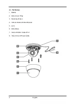
Page 6: ...4 1 Part Names 1 Bubble 2 Dome Cover Ring 3 Mounting Screws 4 Camera Module Gimbal Bracket 5 Lens 6 Dome Base 7 Service Monitor Output Port 8 Video Out and Power Cable 4 English ...

Page 7: ...on the Dome Base for installation of the unit in any place such as a ceiling wall and etc Use the three mounting screws to affix the Dome Base to a sturdy surface To access all three holes rotate the camera module Caution To avoid smear do not expose the camera directly to a strong light source such as the sun or spot light 5 English ...

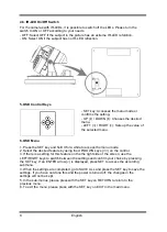
Page 8: ...2V or AC 24V input depending on the camera model All camera models are supplied with a service monitor output on the camera module A control cable is included in the package Note To set up the OSD menu externally a control cable is required 6 English ...

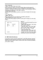
Page 9: ...ust the rotation manually to the desired angle 4 5 Zoom Focus Adjustment 1 If you need to make viewing angle focus adjustments move the levers as shown below First loosen the Zoom Focus levers and then adjust them as needed Field of View Telephoto T to Wide W Focus Near N to Infinity oo 2 After the adjustments are completed tighten the Zoom Focus levers 7 English ...

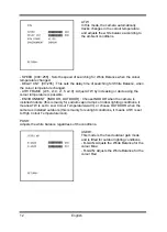
Page 10: ...ss the menu mode 2 Select the desired feature by using the UP DOWN keys on the control 3 If there is a setting for this feature on the the right side of the screen use the LEFT RIGHT keys to switch between the settings and confirm your choice by pressing the SET key If an ENTER arrow is displayed press SET to access the according submenu 4 When the settings are completed go to SAVE ALL and press t...

Page 11: ...r to WDR BACKLIGHT You can control the backlight compensation here NEXT Choose this option to view the second menu page CAMERA ID Here you can assign a unique name or title to the camera MOTION DET This function is used to detect moving objects in the monitoring area PRIVACY You can mask specific areas in the monitoring area here SYNC This function refers to the Internal Syncronisation LANGUAGE He...

Page 12: ...igh the iris might operate improperly MANUAL Select this item for the manual iris lens or the fixed iris lens 6 2 SHUTTER AGC This function is used to control the light exposure You can either select AUTO for the auto iris lens here you can set the shutter value and the brightness level depending on the lighting conditions or you can choose MANUAL for the manual iris lens here you can set up the e...

Page 13: ... 00 Sets the value of auto exposure operations As the value increases the screen gets brighter MANUAL Here you can set the SHUTTER value and the AGC value MODE SHUTTER AGC The mode is fixed to SHUTTER AGC SHUTTER NTSC 1 60 1 100 1 250 1 500 1 1000 1 2000 1 4000 1 1000 PAL 1 50 1 120 1 250 1 10000 Choose the desired value AGC 6 00 12 00 18 00 24 00 30 00 36 00 42 00 44 80 As the AGC value increases...

Page 14: ...temperature is possible ENVIRONMENT INDOOR OUTDOOR Choose INDOOR when the camera is installed indoors this is mainly for sodium vapor lamps or indoor lighting conditions it means ATW is set to Low Colour Temperature warm or choose OUTDOOR when the camera is installed outdoors this is mainly for sunlight conditions it means ATW is set to High Colour Temperature cool PUSH Adjusts the white balance r...

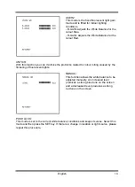
Page 15: ... colour rolling caused by the flickering of fluorescent lights MANUAL This function allows the white balance to be adjusted manually An increased level produces a strong blue tone on the screen and a decreased level produces a strong red tone on the screen PUSH LOCK This mode is set to the current white balance conditions and keeps its value Select this mode and then press the SET key If there is ...

Page 16: ...he displayed image GAIN 000 255 This function is used to adjust the saturation of the displayed image 6 5 NR Noise Reduction NR MODE OFF Y C Y C This function is used to improve the picture quality by filtering the noise which is generated under low bright light conditions You can set up Y luminance C chroma and Y C mode as well as adjust the the filtering level s for each mode 6 6 ATR Adaptive To...

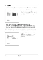
Page 17: ...C High Light Compensation This function is used to surpress or mask a strong light source for example headlights of cars during night time so that other subjects can be seen in more detail 6 8 CAMERA ID This menu is used to assign a unique name to a camera You can enter up to 52 alphanumeric or special characters for the CAMERA ID Select POS and press the SET key to be able to move the display pos...

Page 18: ...ched BURST Set this option to ON to output a burst signal in B W mode DELAY CNT Sets the delay time for switching between COLOR and B W mode DAY NIGHT Sets the brightness level for switching from COLOR to B W mode NIGHT DAY Sets the brightness level for switching from B W to COLOR mode COLOR If set to COLOR the camera will be fixed to COLOR mode regardless of the ambient conditions B W BURST IR OP...

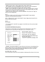
Page 19: ...the camera model GCA B3326D EXT2 Not available The functions EXT1 and EXT2 only appear on the OSD menu of the camera model GCA B3326D 6 10 MOTION DET Motion Detection This function is used to detect moving objects in the monitored area There are 4 predefined boxes representing the areas that can be monitored for motion DETECT SENSE 000 127 Sets the motion detection sensitivity BLOCK DISP OFF ON EN...

Page 20: ...eas If MONITOR AREA in the MOTION DET menu has been set to ON four areas will be selected TOP Sets the top side of the selected mask area BOTTOM Sets the bottom side of the selected mask area LEFT Sets the left side of the selected mask area RIGHT Sets the right side of the selected mask area COLOR 1 8 Choose one of 8 colours for the mask areas TRANSP 0 00 0 5 0 75 1 0 Choose one of 4 transparency...

Page 21: ...ault 6 15 NEXT BACK When you select NEXT the second main menu page will be shown When you select BACK the first main menu page will be shown 6 16 EXIT Exits the menu without saving any changes in the settings 6 17 SAVE ALL Saves the changes in the settings 19 English ...

Page 22: ...l Features H Reverse High Light Compensation Motion Detection On Off OSD Yes DE EN ES FR RU PT JP Camera ID 52 character 2 lines White Balance ATW PUSH Anti CR Manual User 1 User 2 Video Outputs 1 CVBS 1 Vpp BNC 1 test monitor out Humidity less than 90 Operating Temperature 10 C 50 C Supply Voltage 12 VDC 24 VAC 1 7 W Power Consumption 0 32 kg Weight Ø 122 x 95 mm Dimensions wxhxd Specifications G...

Page 23: ...1 7 4 1 LED on W Power Consumption 0 5 kg Weight Ø 122 x 95 mm Dimensions wxhxd Dimensions 21 English ...

Page 24: ...that the products meet the standards in the following relevant provisions EC EMC Directive 2004 108 EC Low Voltage Directive 2006 95 EC Applied harmonised standards and technical specifications EN 55022 2006 A1 2007 EN 50130 4 1995 A1 1998 A2 2003 Ludwig Bergschneider CEO Remscheid 09 02 2012 ASP AG Lüttringhauser Str 9 42897 Remscheid Germany 22 English ...

Reviews: