Allgemeiner Teil / General Section
MCD 36 / MCD 40
1 - 4
GRUNDIG Service
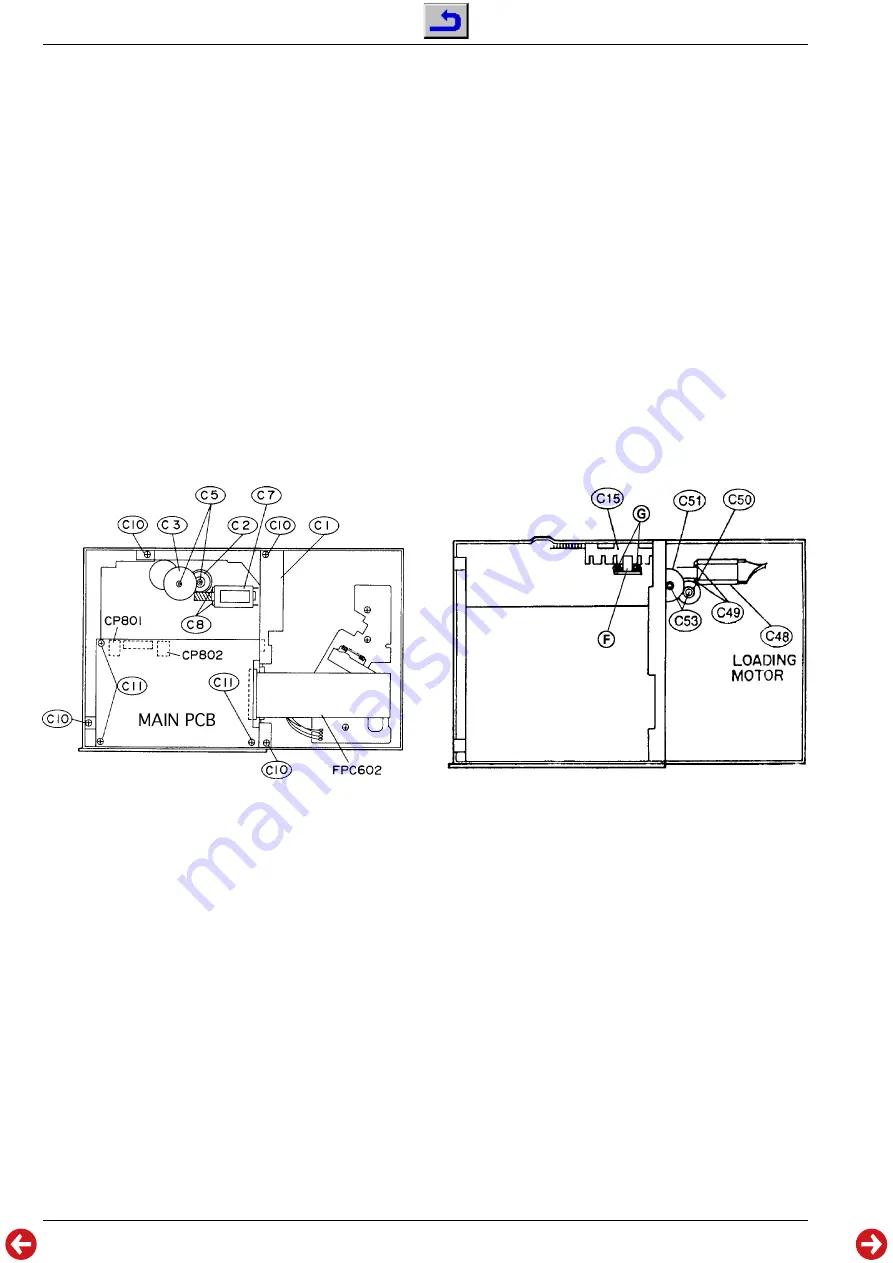
2. Hauptplatte ”MAIN PCB” ausbauen (Fig. 2)
- Gehäuseoberteil abnehmen (Pkt. 1).
- 3 Schrauben
C11 herausschrauben.
- Steckverbindungen lösen.
- Leiterplatte herausnehmen.
3. Ausbau des Lift-Motors C7 (Fig. 2)
- Hauptplatte ”MAIN PCB” ausbauen (Pkt 2).
- Kunststoffscheiben
C5 abziehen.
- Zahnräder
C2 und C3 abnehmen.
- 2 Schrauben
C8 herausschrauben.
- Lift-Motor
C7 ablöten und herausnehmen.
4. Ausbau des Loading-Motors C48
- Hauptplatte ”MAIN PCB” ausbauen (Pkt 2).
- 4 Schrauben
C10 herausschrauben und Magazinschacht-Oberteil
C1 herausnehmen (Fig. 2).
- Kunststoffscheiben
C53 abziehen (Fig. 3).
- Zahnräder
C50 und C51 herausnehmen (Fig. 3).
- 2 Schrauben
C49 herausschrauben (Fig. 3).
- Loading-Motor
C48 ablöten und herausnehmen (Fig. 3).
5. Ausbau des Optokopplers
J
- Hauptplatte ”MAIN PCB” ausbauen (Pkt 2).
- 4 Schrauben
C10 herausschrauben und Magazinschacht-Oberteil
C1 herausnehmen (Fig. 2).
- 2 Schrauben
I
herausschrauben (Fig. 3).
- Optokoppler
J
ablöten und herausnehmen.
Fig. 2
Fig. 3
6. CD-Leiterplatte PCB3 und Pick-Up-Einheit C87 ausbauen
-
Wichtig: Vor dem Ausbau der Pick-Up-Einheit müssen die bei-
den Lötstellen auf der Pick-Up-Einheit kurzgeschlossen wer-
den! (Fig. 4)
- Gehäuse zerlegen (Pkt. 1).
- Steckverbindungen
FPC602, CS901, CP904 und CP906 lösen
(Fig. 5).
- 3 Schrauben
C73 herausschrauben (Fig. 5).
- Schraube
C97 und Schraube C96 herauschrauben (Fig. 6).
- Achse
C90 herausziehen (Fig. 6).
- Pick-Up-Einheit herausnehmen.
- Steckverbindung
FPC601 lösen (Fig. 4) und CD-Leiterplatte PCB3
herausnehmen.
7. Disc-Motor C72 ausbauen (Fig. 6)
- Pick-Up-Einheit ausbauen (Pkt. 6).
- 2 Schrauben
C77 herausschrauben und Disc-Motor herausneh-
men.
2. Removing the Main Board (Fig. 2)
- Remove the upper part of the cabinet (para 1).
- Undo 3 screws
C11.
- Unplug all connectors.
- Take out the PCB.
3. Removing the Lift Motor C7
- Remove the Main Board (para 2).
- Loosen and remove the plastic washers
C5.
- Pull off the gear wheels
C2 and C3.
- Undo 2 screws
C8.
- Unsolder the Lift Motor
C7 and take it out.
4. Removing the Loading Motor C48
- Remove the Main Board (para 2).
- Undo 4 screws
C10 and remove the cover plate of the CD magazine
compartment
C1 (Fig. 2).
- Loosen and remove the plastic washers
C53 (Fig. 3).
- Pull off the gear wheels
C50 and C51 (Fig. 3).
- Undo 2 screws
C49 (Fig. 3).
- Unsolder the Lift Motor
C48 and take it out (Fig. 3).
5. Removing the Opto Coupler
J
- Remove the Main Board (para 2).
- Undo 4 screws
C10 and remove the cover plate of the CD magazine
compartment
C1 (Fig. 2).
- Undo 2 screws
I
(Fig. 3).
- Unsolder the Opto Coupler
J
and take it out.
6. Removing the CD Board PCB3 and the Pick Up Unit C87
-
Important: Before removing the Pick Up Unit the two solder tags
on the Pick Up Unit must be connected (Fig. 4).
- Disassemble the cabinet (para 1).
- Unplug the connectors
FPC602, CS901, CP904 and CP906 (Fig. 5).
- Undo 3 screws
C73 (Fig. 5).
- Undo screws
C97 and C96 (Fig. 6).
- Pull out the shaft
C90.
- Take out the Pick Up Unit.
- Unplug the connector
FPC601 (Fig. 4) and take out the CD Board
PCB3.
7. Removing the Disc Motor C72 (Fig. 6)
- Remove the Pick Up Unit (para 6).
- Undo 2 screws
C77 and remove the Disc Motor.


