Eng
lish (US)
26
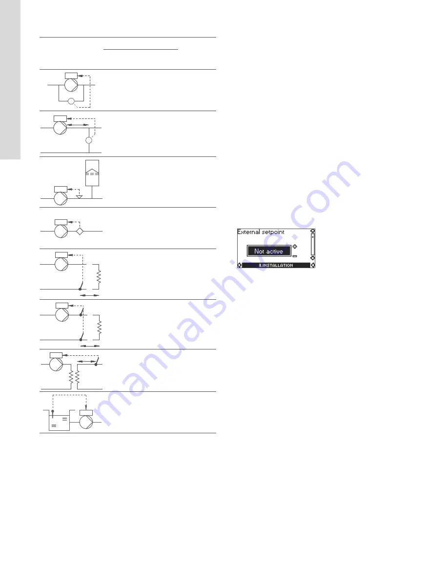
The table below shows the suggested controller settings:
How to set the PI controller
For most applications, the factory setting of the controller
constants K
p
and T
i
will ensure optimum pump operation.
However, in some applications an adjustment of the controller
may be needed.
Proceed as follows:
1. Increase the gain (K
p
) until the motor becomes unstable.
Instability can be seen by observing if the measured value
starts to fluctuate. Furthermore, instability is audible as the
motor starts hunting up and down.
Some systems, such as temperature controls, are slow-
reacting, meaning that it may be several minutes before the
motor becomes unstable.
2. Set the gain (K
p
) to half of the value which made the motor
unstable. This is the correct setting of the gain.
3. Reduce the integral time (T
i
) until the motor becomes
unstable.
4. Set the integral time (T
i
) to twice the value which made the
motor unstable. This is the correct setting of the integral time.
General rules of thumb:
• If the controller is too slow-reacting, increase K
p
.
• If the controller is hunting or unstable, dampen the system by
reducing K
p
or increasing T
i
.
19.3.3 External setpoint
The input for external setpoint signal can be set to different signal
types.
Select one of the following types:
• 0-10 V
• 0-20 mA
• 4-20 mA
• Not active.
If Not active is selected, the setpoint set by means of the R100 or
on the control panel will apply.
If one of the signal types is selected, the actual setpoint is
influenced by the signal connected to the external setpoint input.
See section
23. External setpoint signal
on page
36
.
System/application
K
p
T
i
Heating
systems
ღ
Cooling
systems
ღ ღ
0.5
0.5
0.5
L
1
< 16.4 ft:
0.5
L
1
> 16.4 ft:
3
L
1
> 32.8 ft:
5
0.5
0.5
0.5
0.5
0.5
-0.5
10 + 1.5L
2
0.5
10 + 1.5L
2
0.5
-0.5
30 + 1.5L
2
+2.5
100
ღ
Heating systems are systems in which an increase in
pump performance will result in a
rise
in temperature at
the sensor.
ღ ღ
Cooling systems are systems in which an increase in
pump performance will result in a
drop
in temperature at
the sensor.
L
1
= Distance in [ft] between pump and sensor
L
2
= Distance in [ft] between heat exchanger and sensor
'
p
'
p
L
1
[ft]
p
Q
t
L L
2
[ft]
'
t
L
2
[ft]
t
L
2
[ft]
Summary of Contents for VLSE
Page 2: ...Table of contents 2 VLSE Pump Information 3 Motor information 12...
Page 44: ...44...
Page 45: ...45...
Page 46: ...46...


