background image

A

ppend

ix

39

Appendix

1

Safety declaration

Please copy, fill in and sign this sheet and attach it to the pump returned for service.

Fault description

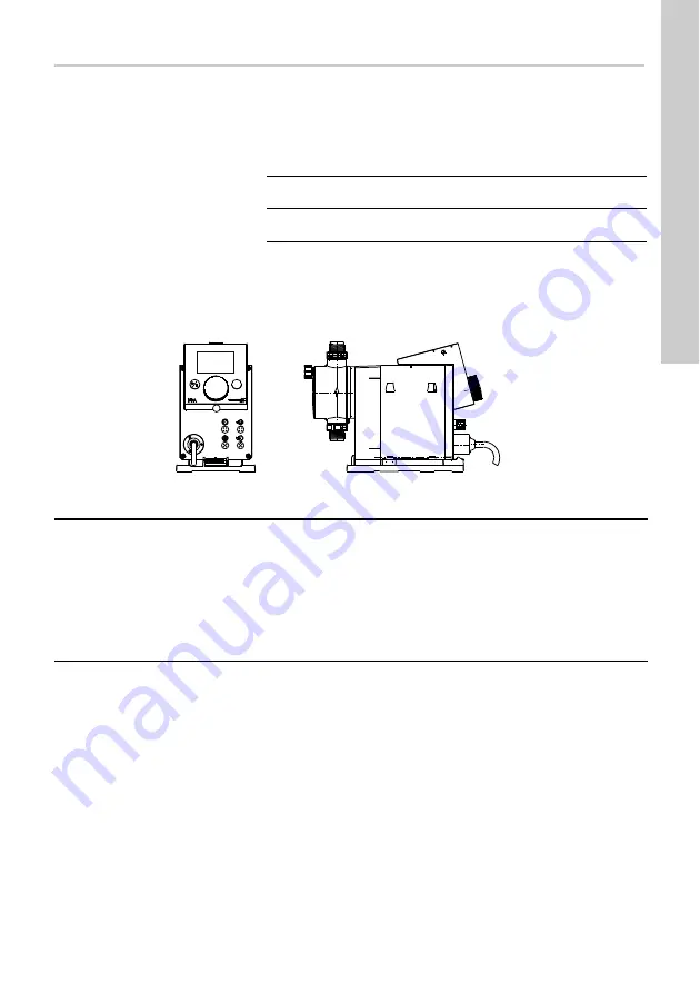
Please make a circle around the damaged parts.
In the case of an electrical or functional fault, please mark the cabinet.

Please describe the error / cause of the error in brief.

We hereby declare that the pump has been cleaned and is completely free from chemical, biological and 
radioactive substances.

_____________________________________
Date and signature

_____________________________________
Company stamp

Product type (nameplate)

Model number (nameplate)

Dosing medium

T

M

04

 1

1

8

5 1

1

10

100%

Summary of Contents for SMART Digital DDA

Page 1: ...GRUNDFOS INSTRUCTIONS SMART Digital DDA Installation and operating instructions...

Page 2: ...y Directive 2006 42 EC Standards used EN 809 1998 EN ISO 12100 1 A1 2009 EN ISO 12100 2 A1 2009 Low Voltage Directive 2006 95 EC Standard used EN 60204 1 A1 2009 EMC Directive 2004 108 EC Standards us...

Page 3: ...y saving mode 19 6 2 4 Overview of display symbols 20 6 3 Main menus 21 6 3 1 Operation 21 6 3 2 Info 21 6 3 3 Alarm 21 6 3 4 Setup 21 6 4 Operation modes 22 6 4 1 Manual 22 6 4 2 Pulse 22 6 4 3 Analo...

Page 4: ...national regulations on health protection environmental protection and for accident prevention and any internal working operating and safety regulations of the operator must be observed Information a...

Page 5: ...ng with chemicals the accident prevention regulations applicable at the installation site should be applied e g wearing protective clothing Observe the chemical manufacturer s safety data sheets and s...

Page 6: ...ual The pump is not dismantled or incorrectly handled The maintenance is carried out by authorised and qualified personnel Original spare parts are used for repairs during maintenance 2 4 Nameplate Fi...

Page 7: ...VC with Plus3 E V T Gasket material EPDM FKM PTFE C SS Valve ball material Ceramic Stainless steel DIN 1 4401 F Control cube position Front mounted can be changed to the right or left 3 Voltage 1 x 10...

Page 8: ...ontrol cube Graphic LC display Sect 6 2 2 Click wheel Sect 6 1 100 key Sect 6 1 Signal inputs outputs Sect 4 3 Mounting plate 100 100 TM04 1133 0110 FlowControl connection FC FCM Deaeration valve Dosi...

Page 9: ...Max suction lift when priming with wet valves 2 m 2 3 3 2 Min pressure difference between suction and discharge side bar 1 FC and FCM 2 Max pressure suction side bar 2 Max viscosity in SlowMode 25 wi...

Page 10: ...safety class II Signal input Max load for level input 12 V 5 mA Max load for pulse input 12 V 5 mA Max load for external stop 12 V 5 mA Min pulse length ms 5 Max pulse frequency Hz 100 Impedance at 0...

Page 11: ...Dimensional drawing TM04 1103 0110 161 17 D B C A1 G 5 8 A 200 8 100 110 4 x 6 105 120 17 5 168 Pump type A mm A1 mm B mm C mm D mm DDA 7 5 16 280 251 196 46 5 24 DDA 12 10 17 7 280 251 200 5 39 5 24...

Page 12: ...wall on the bracket or the tank 4 1 3 Engage pump in mounting plate 1 Attach the pump to the mounting plate support clamps and slide under slight pressure until it engages Fig 6 Engaging the pump 4 1...

Page 13: ...the corresponding connection see fig 3 and run into a container or a collecting tray Fig 8 Hydraulic connection Installation example The pump offers various installation options In the picture below...

Page 14: ...am of the electrical connections Warning The enclosure class IP65 Nema 4X is only guaranteed if plugs or protective caps are correctly installed Warning The pump can start automatically when the mains...

Page 15: ...Analog GND mA mA mA signal External stop GND X Pulse Pulse GND X Pulse Function Pins Plug type 1 brown 2 white 3 blue 4 black Low level signal X GND Pulse Empty signal X GND Pulse Function Pins Plug t...

Page 16: ...Press the click wheel to select the highlighted language 7 Press the click wheel again to confirm the Confirm settings prompt and apply the setting Fig 12 Set menu language TM04 1184 1110 Operation E...

Page 17: ...th FCM control variant it is not necessary to calibrate the pump if there is deviating or fluctuating backpressure as long as the AutoFlowAdapt function has been enabled see section 6 10 AutoFlowAdapt...

Page 18: ...n value e g 125 ml 6 Remove the suction hose from the measuring beaker and check the remaining volume V2 e g 170 ml 7 From V1 and V2 calculate the actual dosed volume Vd V1 V2 e g 300 ml 170 ml 130 ml...

Page 19: ...yed as symbols The position of the cursor is highlighted in black in the sub menus When you position the cursor on a value and press the click wheel a value is selected Turning the clickwheel clockwis...

Page 20: ...Sect 6 4 1 Pulse Sect 6 4 2 Analog 0 4 20 mA Sect 6 4 3 Batch Sect 6 4 4 Timer Sect 6 4 5 6 4 6 Running Standby Stop Deaerating Diaphragm position out Sect 7 Additional display Sect 6 13 2 AR FC varia...

Page 21: ...displayed for specific default settings and control variants The contents of the Setup menu also vary depending on the operation mode TM04 1157 1010 TM04 1106 1010 Counters resettable Volume Total dos...

Page 22: ...ng the set volume per pulse The calculation is based on the frequency of external pulses the set dosing volume pulse Fig 16 Pulse operation mode The dosing volume per pulse is set in ml pulse using th...

Page 23: ...ient In example 1 the reference points I1 6 mA Q1 1 5 l h and I2 16 mA Q2 7 5 l h have been set From 0 to 6 mA analog scaling is described by a line that passes through Q 0 l h between 6 mA and 16 mA...

Page 24: ...mode If the batch volume is modified the dosing time resets to the minimum dosing time Signals received during a batch process or an interruption e g alarm external stop will be ignored If the pump i...

Page 25: ...time until the next dosing process e g 1 21 is displayed Fig 27 Dos Timer Cycle mode 6 4 6 Dosing timer week In this operation mode up to 16 dosing procedures are defined for a week These dosing proc...

Page 26: ...viscosity for degassing dosing media for long suction lines for large suction lift In the Setup SlowMode menu the speed of the suction stroke can be reduced to 50 or 25 Fig 32 SlowMode menu TM04 1136...

Page 27: ...from the current measured values and the current diaphragm position stroke length Causes for deviations can be identified immediately by aligning the current indicator diagram with a calculated optim...

Page 28: ...bration is not successfully possible check plug connections cable and sensor and replace defective parts where necessary Caution The pump restarts automatically once the backpressure falls below the c...

Page 29: ...on 6 8 Pressure monitoring Flow measurement deviations from the target flow are identified see section 6 8 2 Calibration of pressure sensor Examples of AutoFlowAdapt Pressure fluctuations The dosing v...

Page 30: ...isplayed 6 13 2 Additional display Additional display provides additional information about the current pump status The value is shown in the display with the corresponding symbol In Manual mode the A...

Page 31: ...lay 1 2 and the signal inputs External stop Empty signal and Low level signal Fig 36 Setup Inputs outputs menu 6 16 1 Relay outputs The pump can switch two external signals using installed relays The...

Page 32: ...evel in the tank a dual level sensor can be connected to the pump The pump responds to the signals as follows Both signal inputs are allocated to the closed contact NO in the factory They can be re al...

Page 33: ...ned 7 2 Perform service Only spare parts and accessories from Grundfos should be used for maintenance The usage of non original spare parts and accessories renders any liability for resulting damages...

Page 34: ...ange valves and pay attention to direction of arrow 7 Connect suction pressure and deaeration hose see section 4 2 Hydraulic connection 8 Press the Start Stop key to leave the service mode 9 Deaerate...

Page 35: ...d display indicates an alarm and the pump is stopped The last 10 faults are stored in the Alarm main menu When a new fault occurs the oldest fault is deleted The two most recent faults are shown in th...

Page 36: ...g Broken leaky suction line Strongly degassing medium Tank dosing medium empty Check suction line and repair if necessary Provide positive inlet pressure place dosing medium tank above the pump Enable...

Page 37: ...rs if necessary Bus Warning alarm Fieldbus communication error Check cables for correct specification and damage replace if necessary Check cable routing and shielding correct if necessary E Box Alarm...

Page 38: ...uction line Clean suction line install filter Suction lift too high Reduce suction lift Install priming aid Enable Slow Mode see section 6 6 SlowMode Viscosity too high Enable Slow Mode see section 6...

Page 39: ...rical or functional fault please mark the cabinet Please describe the error cause of the error in brief We hereby declare that the pump has been cleaned and is completely free from chemical biological...

Page 40: ...40...

Page 41: ...41...

Page 42: ...0 51 Germany GRUNDFOS Water Treatment GmbH Reetzstra e 85 D 76327 Pfinztal S llingen Tel 49 7240 61 0 Telefax 49 7240 61 177 E mail gwt grundfos com Germany GRUNDFOS GMBH Schl terstr 33 D 40699 Erkrat...

Page 43: ...1 848 8800 Telefax 34 91 628 0465 Sweden GRUNDFOS AB Box 333 Lunnag rdsgatan 6 431 24 M lndal Tel 46 0 771 32 23 00 Telefax 46 0 31 331 94 60 Switzerland GRUNDFOS ALLDOS International AG Sch nmattstra...

Page 44: ...ovation is the essence www grundfosalldos com The name Grundfos the Grundfos logo and the payoff Be Think Innovate are registrated trademarks owned by Grundfos Management A S or Grundfos A S Denmark A...

Reviews: