E
ngl
ish (
G
B)
19
6. Operation
6.1 Control elements
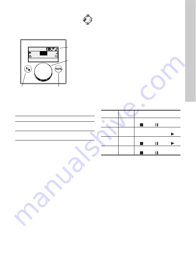
The pump control panel includes a display
and the following control elements.
Fig. 13
Control panel
Keys
Click wheel
The click wheel is used to navigate through the
menus, select settings and confirm them.
Turning the clickwheel clockwise moves the cursor
clockwise in increments in the display. Turning the
clickwheel anti-clockwise moves the cursor anti-
clockwise.
6.2 Display and symbols
6.2.1 Navigation
In the
’Info’
,
’Alarm’
and
’Setup’
main menus, the
options and submenus are displayed in the rows
below. Use the
’Back’
symbol to return to the higher
menu level. The scroll bar at the right edge of the
display indicates that there are further menu items
which are not shown.
The active symbol (current cursor position) flashes.
Press the click wheel to confirm your selection and
open the next menu level. The active main menu is
displayed as text, the other main menus are
displayed as symbols. The position of the cursor is
highlighted in black in the sub-menus.
When you position the cursor on a value and press
the click wheel, a value is selected. Turning the
clickwheel clockwise increases the value, turning the
clickwheel anti-clockwise reduces the value. When
you now press the click wheel, the cursor will be
released again.
6.2.2 Operating states
The operating state of the pump is indicated by a
symbol and display colour.
6.2.3 Sleep mode (energy-saving mode)
If in the
’Operation’
main menu the pump is not
operated for 30 seconds, the header disappears.
After 2 minutes, the display switches to the
’Operation’
main menu and the display brightness is
reduced. This state will be cancelled when the pump
is operated or a fault occurs.
T
M
04 1
104
1
120
Key
Function
Start/stop
key
Starting and stopping the pump.
100 % key
The pump doses at maximum flow
regardless of the operation mode.
100%
7.49 l/h
Manual
7.50
l/h
Operation
Start/stop key
Graphical LC
display
Click wheel
100 % key
Display
Fault
Operating state
White
-
Stop Standby
Green
-
Running
Yellow
Warning
Stop Standby
Running
Red
Alarm
Stop Standby
Summary of Contents for SMART Digital DDA
Page 1: ...GRUNDFOS INSTRUCTIONS SMART Digital DDA Installation and operating instructions...
Page 40: ...40...
Page 41: ...41...


