


14 |
P a g e
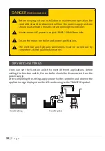
Users can set the function switch to suit different applications. Before
setting the function switch, the unit should be disconnected from the
power supply. After completing the settings of dip switches, power may be
applied to the unit. The symbol corresponding to the application will be
displayed on the LCD Screen.
Drainage Setting
Switches Down
Drainage Symbol
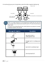
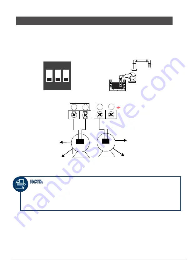
Pump connection for over temperature protection (where supplied with pump)
Pump Shell
19 20
Jumpers Lead
Pump Shell
Over Temperature
(Thermal)Switch
Pump A
Pump B
Over Temperature
(Thermal)Switch
DIP SWITCH SETTINGS
NOTE:
To enable the pump’s over temperature protection connect the
pump’s thermistor leads to terminals 14 and 15, 19 and 20 and remove
the jumper.
If the pump is without thermistor switch, please use jumper to connect
terminals 14 and 15, 19 and 20.
14
15
ON
1 2 3


