13 |
P a g e
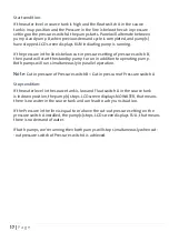
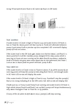
Start condition:
If the liquid level in the pit/tank rises, ie. Float A is in up position. Panel will start
pump A. Panel will alternate between pump A and pump B after previous cycle is
completed. LCD screen will display RUN whichever pump in running.
If the liquid level in the pit/tank rises even further after first pump is running ie.
Float Switch A and Float switch B are in up position. As soon as Float switch B
reaches up position, panel will start whichever pump is in standby. Eg. If pump A
was running and liquid level rose even further and Float B comes in up position,
pump B will also start operating in parallel to pump A.
Alarm condition:
If the liquid level in the pit/tank rises even further after both pumps are running
and Float switch C is in up position. In this situation in addition to both pumps
running, an overflow alarm will generate an audio-visual sound with fault indica-
-tion on LCD screen showing Overflow. This fault will reset itself only when liquid
level in pit/tank falls below Float C, and Float C is in down position.
Stop condition:
If the liquid level in the pit/tank falls, ie. Float A is in down position. Panel will
stop whichever pump is running. This means that there is not enough water to
pump. LCD screen will display No water.
If both pumps, we're running, then both pumps will stop simultaneously when
float switch A is in down position. LCD screen will display No water.
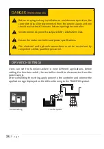
DANGER
Electric shock risk.
Before carrying out any installation or maintenance operation, the
controller should be disconnected from the power supply and the
person should wait at least 2 minutes before opening the controller.
Never connect AC power to output L1&N1 / L2&N2 terminals.
Ensure the motor, controller and power specifications match.
The electrical and hydraulic connections must be carried out by
competent, skilled, qualified personnel.


