English (GB)
21
10.6 Fault finding chart
11. Maintenance
11.1 General notes
11.2 Cleaning and maintenance intervals
11.2.1 Changing the gear grease
To ensure trouble-free operation, it is recommended to have the
gear grease changed after five years or after 20000 operating
hours.
11.2.2 Cleaning the diaphragm and valves
Clean the diaphragm and valves, and replace if necessary
(with stainless-steel valves: inner valve parts):
• At least every 12 months or after 4000 operating hours.
When operating with a counterpressure of 16 bar, every six
months or after 2000 operating hours.
• In the event of a fault.
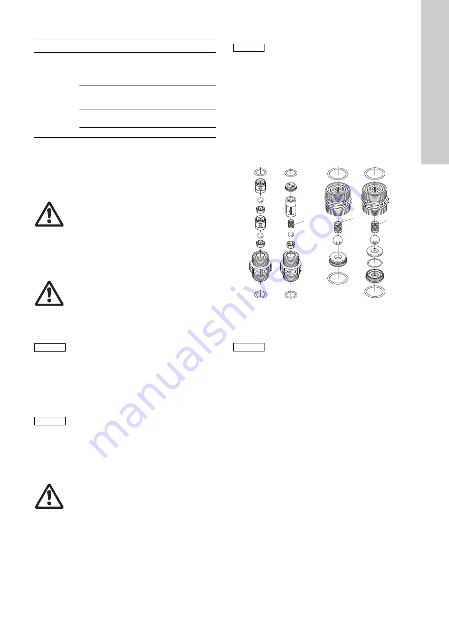
11.3 Cleaning the suction and discharge valves
If the pump loses capacity, clean the suction and discharge
valves as follows:
1. Unscrew the valve.
– DN 20
Unscrew the screw part resp. valve seat with round pliers.
– DN 8
Press out the valve cartridge and remove the valve seat
from the ball cage.
2. Clean all parts. Replace faulty parts by new ones.
3. Re-assemble the valve.
4. Replace the O-rings by new ones. Refit the valve.
Observe the direction arrow on the valve.
Fig. 26
Stainless-steel or plastic valve DN 8 / DN 20,
* spring-loaded as an option
11.4 Maintenance of the relief valve
11.4.1 Cleaning and maintenance intervals
Clean the relief valve, and replace the diaphragm, if necessary.
• At least every 12 months or after 8000 operating hours.
• In the event of a fault.
11.4.2 Replacing the diaphragm of the relief valve
1. Switch off the pump and disconnect it from the power supply.
2. Make it impossible for a return flow or overpressure to occur.
3. Loosen the four screws on the top part of the relief valve.
4. Remove the top part of the relief valve.
5. Remove the diaphragm.
6. Insert a new diaphragm.
7. Refit the top part of the relief valve and cross-tighten the
screws.
Maximum torque: 6 Nm.
8. Start up the dosing system.
9. Tighten the screws on the top part of the relief valve after
48 operating hours.
Maximum torque: 6 Nm.
Fault
Cause Remedy
Permanent
output from
the relief
valve.
Discharge line
blocked.
Check and possibly
correct the
discharge-side dosing
system.
Relief valve incorrectly
set (too low).
Set the relief valve to a
higher opening
pressure.
Diaphragm faulty.
Replace the
diaphragm.
Relief valve dirty.
Clean the relief valve.
Warning
When dosing dangerous media, observe the
corresponding safety precautions!
Risk of chemical burns!
Wear protective clothing (gloves and goggles)
when working on the dosing head, connections
or lines!
Do not allow any chemicals to leak from the
pump. Collect and dispose of all chemicals
correctly!
Warning
The pump housing must only be opened by
personnel authorised by Grundfos!
Repairs must only be carried out by authorised
and qualified personnel!
Switch off the pump and disconnect it from the
power supply before carrying out maintenance
work and repairs!
Caution
For transport or cleaning, the venting cartridge
must be closed.
Before start-up, open the venting cartridge
(pull cap approx. 5 mm).
Caution
In the event of a diaphragm leakage, the dosing
liquid may leak out of the hole in the intermediate
flange between the pump and the dosing head.
The parts inside the housing are protected from
the dosing liquid for a short time (depending on
the type of liquid) by the housing sealing. It is
necessary to check regularly (daily) if liquid is
leaking out of the intermediate flange.
For maximum safety, we recommend the pump
version with diaphragm leakage detection.
Warning
The gear grease must only be changed by
authorised and qualified personnel.
For this purpose, send the pump to Grundfos or
an authorised service workshop.
Caution
If possible, rinse the dosing head, e.g. by
supplying it with water.
T
M
04
83
8
4
09
11
Caution
The O-rings must be correctly placed in the
specified groove.
Observe the flow direction (indicated by an arrow
on the valve)!
DN 20
DN 8
*
*
*


